Controlled kinetic energy ion source for miniature ion trap and related spectroscopy system and method

a technology of kinetic energy ion source and miniature ion trap, which is applied in the field of ion sources, can solve the problems of degrading resolution, unable to create ions in such systems, and devices currently have limited application

Active Publication Date: 2006-12-07
UT BATTELLE LLC
View PDF13 Cites 19 Cited by
  • Summary
  • Abstract
  • Description
  • Claims
  • Application Information

AI Technical Summary

Benefits of technology

[0015] A method of controlling translational ion kinetic energy, comprises the steps of providing a resistive drift tube coupled to an ion trap or ion trap array, injecting ions generated by an ion source spaced apart from the resistive drift tube into the resistive drift tube, wherein the ions are decelerated while in the resistive drift tube to provide cooled ions having mean translational kinetic energies less than 5 keV. The cooled ions are then injected into the ion trap or ion trap array. The method can further comprise the step of controlling the average translational kinetic energy using at least one of pressure in the resistive drift tube and the applied field in the resistive drift tube. The method can generally includes the step of injecting the cooled ions in the ion trap or ion trap array into a spectrometer, such as a time-of-flight mass spectrometer or an ion mobility spectrometer.

Problems solved by technology

However, in real TOF-based systems, the ions are initially neither nearly at rest nor in a well defined spatial region.
Also, the resolution is degraded because of the diffusion that takes place during the drift.
However, such devices currently have limited application because translationally hot ions provided by conventional ion sources, such as electrospray or laser ablation and matrix-assisted laser desorption ionization (MALDI), are far too energetic to be trapped in the trap(s).
As a result, ions in such systems can only be created with the trap.
Consequently, such instruments are generally limited to only electron impact of small volatile organic molecules and gas phase testing.

Method used


Image

  • Controlled kinetic energy ion source for miniature ion trap and related spectroscopy system and method
  • Controlled kinetic energy ion source for miniature ion trap and related spectroscopy system and method
  • Controlled kinetic energy ion source for miniature ion trap and related spectroscopy system and method

Examples


examples

[0037] It should be understood that the Examples described below are provided for illustrative purposes only and do not in any way define the scope of the invention.

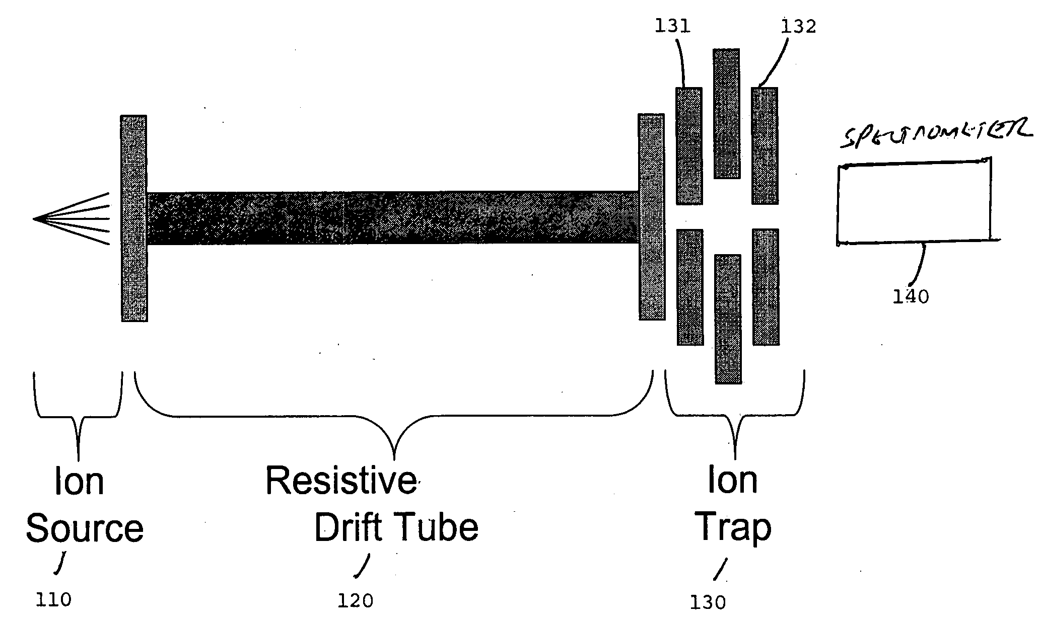
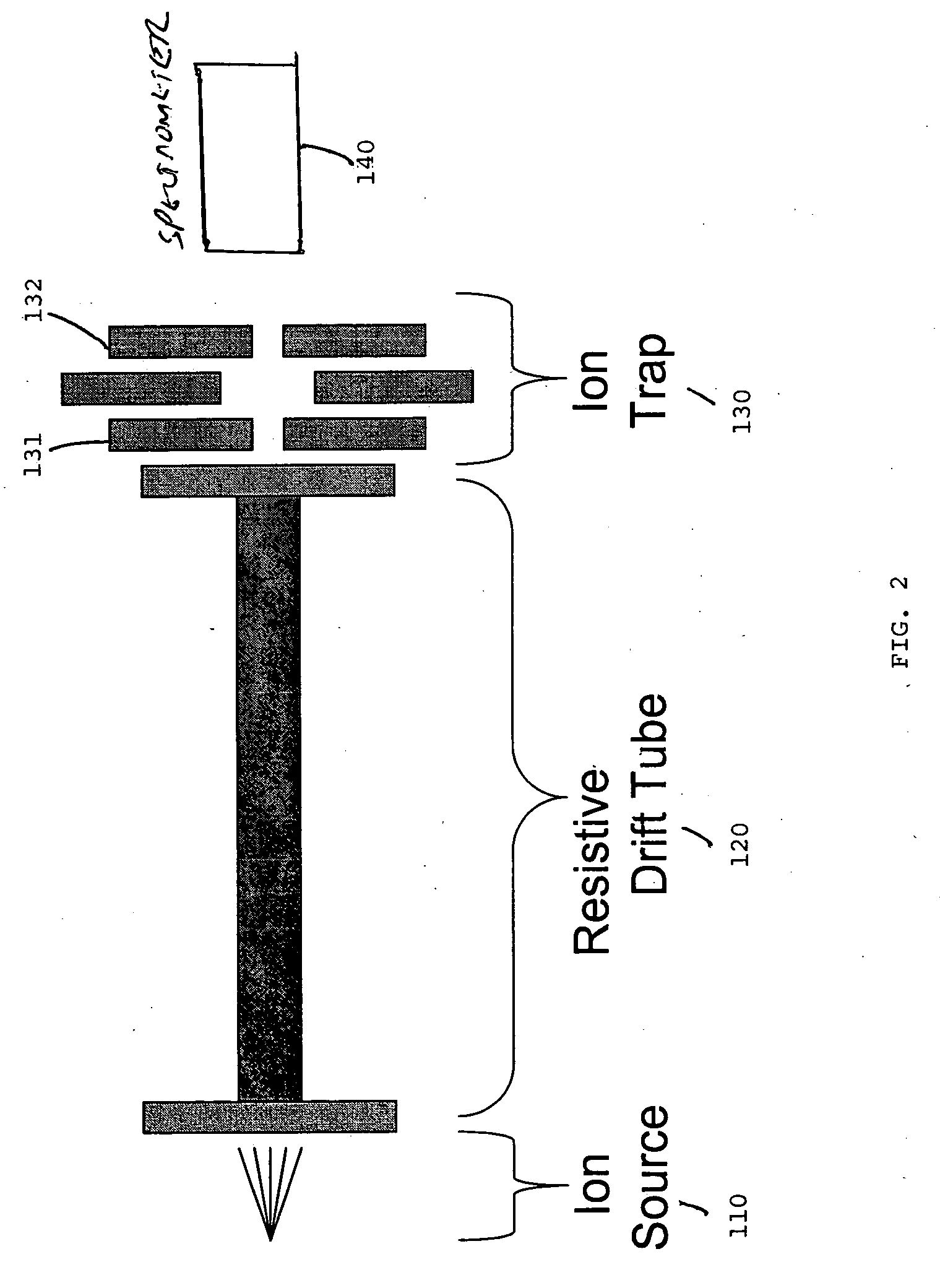
[0038] A mixture of C60 (720 a.u.) and C70 (840 a.u.) fullerite was deposited onto a probe tip. Laser ablation with a N2 laser was employed to ionize the sample. The sample ions were collisionally cooled in a 2 inch long, 0.125 inch ID (0.3 cm), 0.150 OD, RESISTIVE GLASS™ drift tube at 1.0 Torr He. The translational kinetic energy was controlled by varying the pressure and the applied field to the drift tube. The cooled ions were trapped and analyzed using a 1 mm cylindrical ion trap coupled to a channeltron detector which was at 1.0×10⁻⁴ Torr.

[0039]FIG. 3 shows the spectrum recorded by the channeltron detector. Peaks for C60 (720 a.u.) and C70 (840 a.u.) fullerite were identified as shown in FIG. 3.

[0040] FIGS. 4(a)-(c) show simulated results obtained for energy distribution in eV by varying the drift tube applied fi...


PUM


Abstract

An ion trap mass spectrometry system adapted for portability and related method includes an ion source for generating ions from a sample to be analyzed, and a resistive drift tube coupled to an output of the ion source for receiving the ions injected therein. The resistive drift tube decelerates the ions to provide cooled ions having a mean translational kinetic energy of less than 5 keV. A miniature ion trap or trap array, such having apertures <1 mm, is coupled to an output of the resistive drift tube for trapping the cooled ions. A spectrometer is coupled to the miniature ion trap for analyzing the cooled ions.

Description

STATEMENT REGARDING FEDERALLY SPONSORED RESEARCH OR DEVELOPMENT [0001] The United States Government has rights in this invention pursuant to DARPA Contract No. 1868-HH-61-X1.CROSS REFERENCE TO RELATED APPLICATIONS [0002] Not applicable. BACKGROUND OF THE INVENTION [0003] 1. Technical Field [0004] This invention relates to ion sources, and more particularly to controlled kinetic energy ion sources coupled to miniature ion traps or ion trap arrays, and spectroscopy systems based thereon. [0005] 2. Description of the Related Art [0006] Time-of-flight (TOF) mass spectrometry is an analytical technique that is widely used because of its simplicity and wide mass range. In an idealized TOF system, ions are initially confined to a small spatial region and are nearly at rest near an electrode. However, in real TOF-based systems, the ions are initially neither nearly at rest nor in a well defined spatial region. [0007] At certain discrete times, generally denoted as t=0, the ions are accelera...

Claims


Application Information

Patent Timeline
Patent Type & Authority Applications(United States)
IPC IPC(8): H01J49/00
CPCH01J49/062H01J49/0013
Inventor VERBECK, GUIDO F.WHITTEN, WILLIAM B.MOXOM, JEREMY
Owner UT BATTELLE LLC
Why Eureka
Try Eureka