
Cylinder head gasket

Inactive Publication Date: 2006-12-07
ISHIKAWA GASKET CO LTD
View PDF8 Cites 4 Cited by
  • Summary
  • Abstract
  • Description
  • Claims
  • Application Information

AI Technical Summary

Benefits of technology

[0016] According to the structure, the bead between the tightening bolt holes where the surface pressure is easily lowered is partly formed in the pointed shape to the outside in a plan view with respect to the circumferential direction of the bead. As a result, the length of a seal bead of the above-described portion can be made longer in a relatively simple structure, so that the pressure receiving area of the bead can be made larger. Accordingly, the creep relaxation (permanent set in fatigue) of the pointed-shape portion becomes smaller than that of an arc-shaped bead in an usual plan view. Therefore, even between the cylinder bores where heat and so on are high and the sealing condition is bad, or in the portion of an exhaust side, excellent sealing performance can be maintained, and the sealing can be strengthened by using this structure.
[0023] According to the cylinder head gasket of the invention, the pointed-shape portion of the bead provided between the cylinder bores increases the pressure receiving portion, so that the sealing surface pressure between the cylinder bores, or in the intermediate portion of the tightening bolt holes on the exhaust side where the sealing performance of the cylinder head gasket can be easily lowered can be improved in the relatively simple structure.

Problems solved by technology

Since the cylinder head gasket is formed by one or two metal plates, and usable materials are also limited in terms of the lightweight engine, the type and number of sealing means are also limited.
Also, in recent lightweight and small-sized engines, engine rigidity has been decreased, so that in the sealing of the cylinder head gasket, providing a uniform sealing surface pressure around a cylinder bore has become difficult.
More specifically, due to a structural problem around the cylinder bore of an engine member, when the gasket is tightened, there is a shortage of sealing surface pressure at the portion where the rigidity is weak.
As a result, there has been a number of gas leaks in the portion where the rigidity is weak.
When even a small amount of the leaked gas penetrates a water hole or oil hole, the circulation of water or oil is blocked due to the invasion of the gas in a liquid such as water, oil, and so on.
This blockage interferes with the cooling of the engine, and causes engine trouble, so that adequate measures are required.
On the one hand, when a large sealing surface pressure is provided in the nearest peripheral part of the cylinder bore in order to assure the sealing performance of the bore, the deformation of the cylinder bore with low rigidity is accelerated, and the sealing means of the gasket does not function well.
As a result, it is difficult to achieve adequate sealing performance.
The occurrence of the portion where the surface pressure is weak in the unequal surface pressure distribution causes the leakage of the combustion gas.
However, although this structure has the effect of adjusting the surface pressure distribution in the folded portion, the surface pressure distribution in the bead portion cannot be adjusted.
However, in this case, there are problems that relatively high construction accuracy is required for a metal mold for forming the meandering portion; and the folded portion cannot be provided around the cylinder bore due to the obstacle of the meandering portion.

Method used


Image

  • Cylinder head gasket
  • Cylinder head gasket
  • Cylinder head gasket

Examples


first embodiment

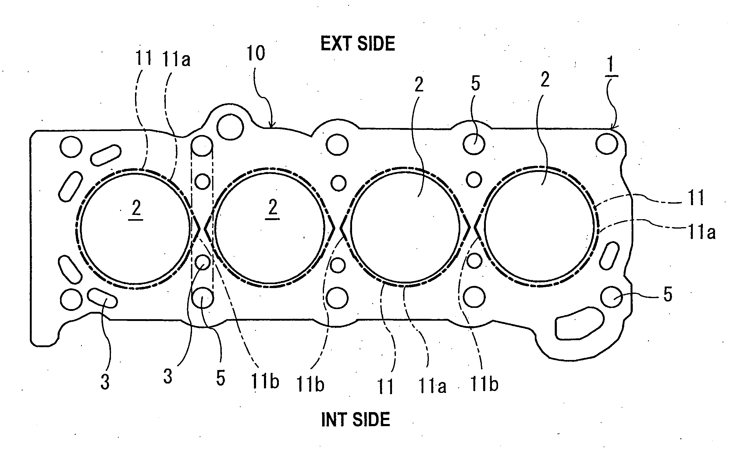
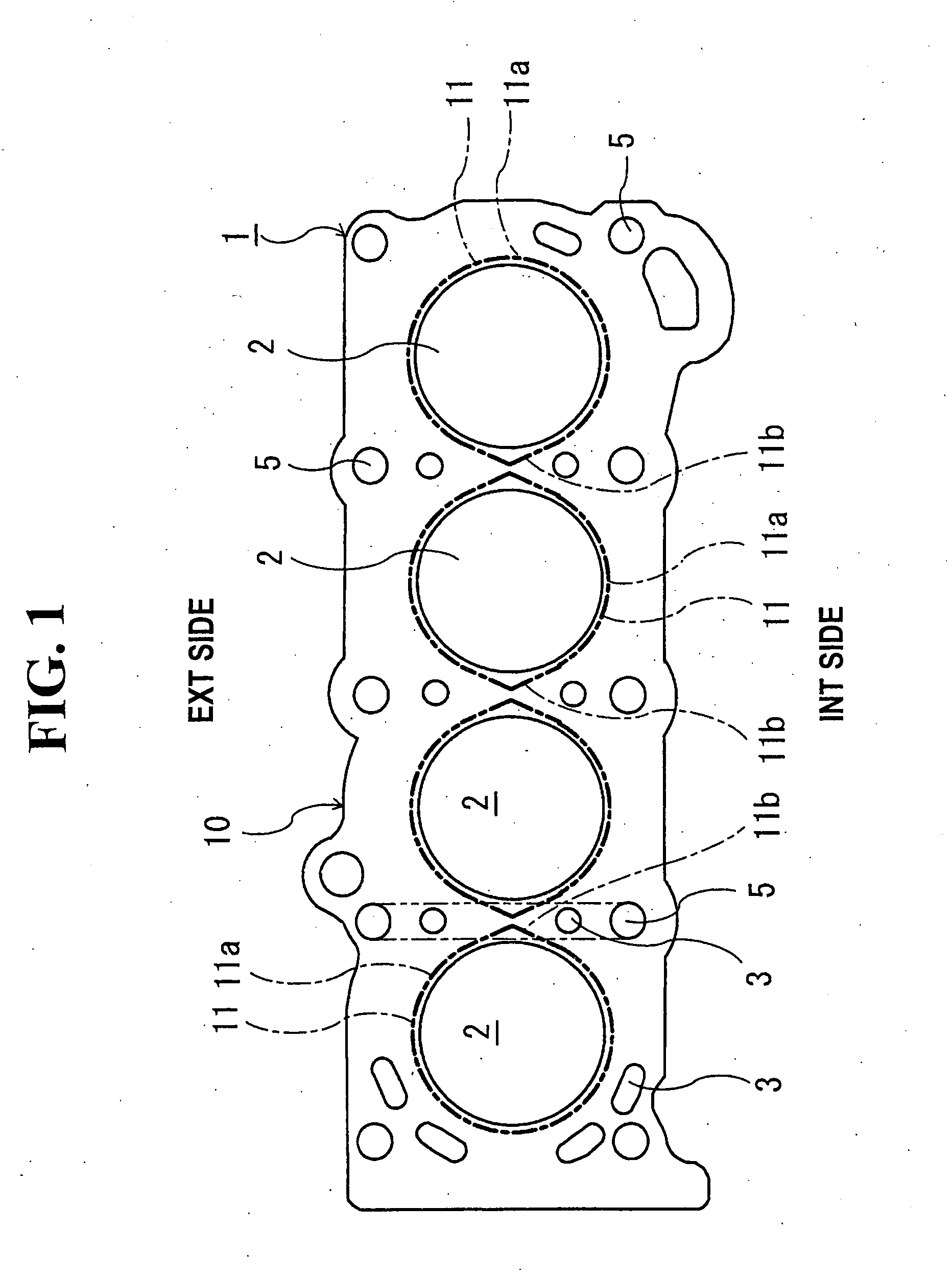
[0033] In a first embodiment, the bead 11 has a partly pointed shape in a circumferential direction in the plan view between the cylinder bores 2, and only in an intermediate portion 11b between the tightening bolt holes 5. A portion 11a other than the intermediate portion 11b is formed in a circular arc shape along the cylinder bore 2 in the plan view.

[0034] According to the structure, since the pressure receiving area of the pointed-shaped portion 11b of the bead 11 provided between the cylinder bores 2 increases, the sealing surface pressure in the portion where the sealing performance can be easily lowered between the cylinder bores 2 of the cylinder head gasket 1 can be improved in a relatively simple structure.

second embodiment

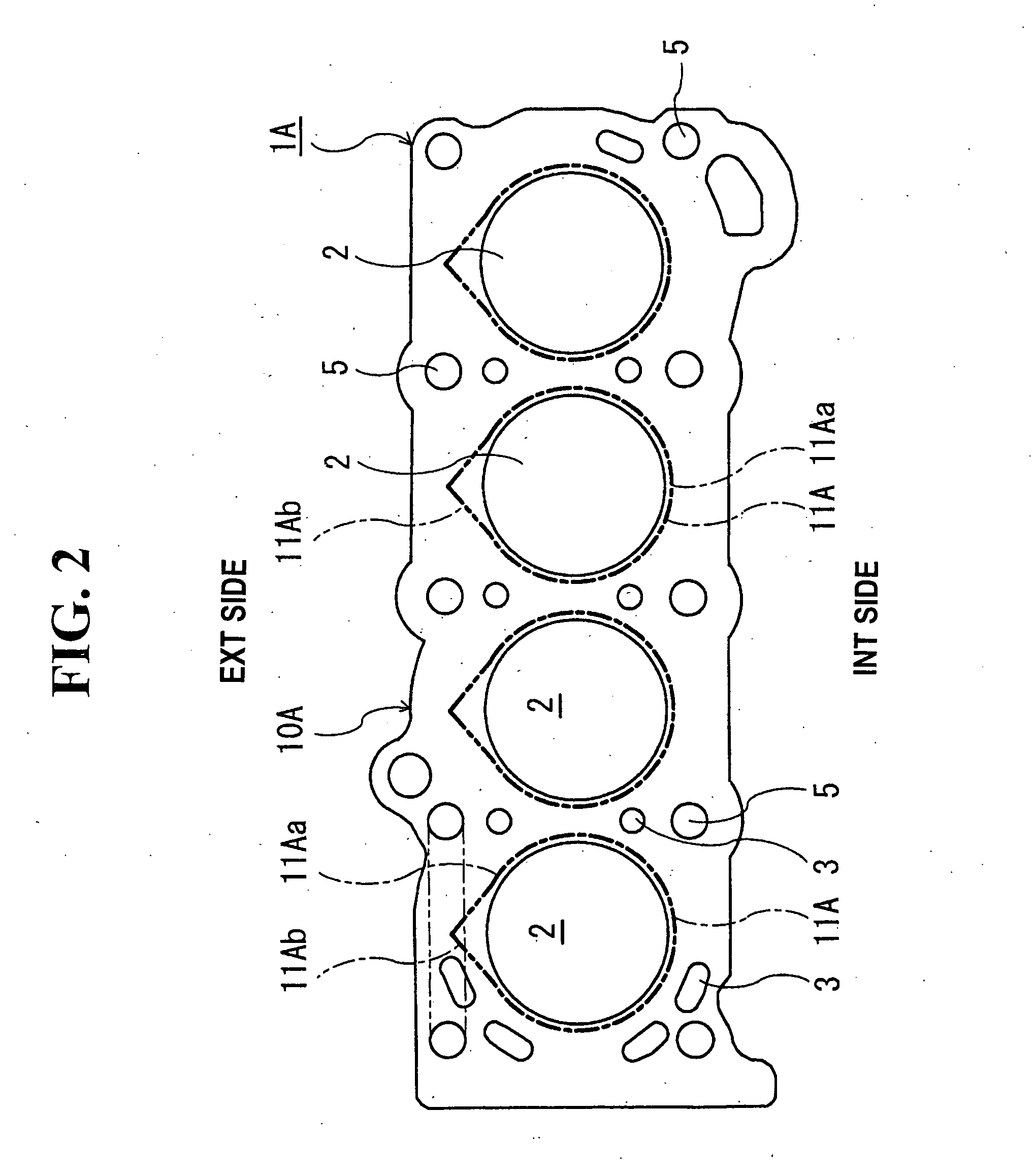
[0035] In a second embodiment, as shown in FIG. 2, in each bead 11A for sealing each cylinder bore 2 of the metal substrate 10A, only an intermediate portion 11Ab between the tightening bolt holes 5 on the exhaust side (EXT side) is formed in a partially pointed shape in the plan view. A portion 11Aa other than the intermediate portion 11Ab is formed in a circular arc shape along the cylinder bore 2 in the plan view.

[0036] According to the structure, on the exhaust side (EXT side) where the sealing performance can be easily lowered due to a high temperature compared to the temperature on the intake side (INT side), the pressure receiving area of the pointed-shaped portion 11Ab of the bead 11A provided between the cylinder bores 2 increases, so that the sealing surface pressure in the portion where the sealing performance can be easily lowered between the tightening bolt holes 5 on the exhaust side (EXT side) can be improved in the relatively simple structure.

third embodiment

[0037] In a third embodiment, as shown in FIG. 3, in each bead 11B for sealing each cylinder bore 2 of the metal substrate 10B, both of the intermediate portions 11Bb, i.e. between the cylinder bores 2, and between the tightening bolt holes 5 on the exhaust side (EXT side) have a partly pointed shape in the plan view. Portions 11Ba other than the intermediate portions 11Bb are formed in a circular arc shape along each cylinder bore 2 in the plan view.

[0038] According to the structure, since the pressure receiving areas of the pointed-shaped portions 11Bb of the bead 11B provided between the cylinder bores 2 and on the exhaust side (EXT side) increase, the sealing surface pressure in the portions where the sealing performance is easily lowered between the cylinder bores 2 and the tightening bolt holes 5 on the exhaust side (EXT side) of the cylinder head gasket 1B can be improved in the relatively simple structure.


PUM


Abstract

A cylinder head gasket includes a metal plate having at least one cylinder bore and a plurality of bolt holes arranged around the at least one cylinder bore. A bead is formed on the metal plate to surround the at least one cylinder bore. The bead has at least one pointed shape portion pointed outwardly between two of the bolt holes.

Description

BACKGROUND OF THE INVENTION AND RELATED ART STATEMENT [0001] The present invention relates to a cylinder head gasket to be installed between two members, such as a cylinder head and a cylinder block of an internal combustion, to seal therebetween. [0002] When the joint surfaces of the cylinder head and cylinder block (cylinder body) of an automobile engine is sealed, a metal cylinder head gasket is installed between the cylinder head and cylinder block and seals combustion gas, coolant water, lubricating oil, and so on. [0003] The above-mentioned cylinder head gasket has been changed from a lamination-type metal cylinder head gasket wherein multiple sheets of metal substrates are laminated, to a cylinder head gasket with a simple structure formed by one or two metal substrates for the needs of a lightweight engine, manufacturing cost reduction, and so on. Since the cylinder head gasket is formed by one or two metal plates, and usable materials are also limited in terms of the lightw...

Claims


Application Information

Patent Timeline
IPC IPC(8): F02F11/00
CPCF16J15/0818F02F11/002F16J15/02
Inventor FUKAI, DAI
Owner ISHIKAWA GASKET CO LTD
Learn More