Electronic instrument and reproduction system

a technology of reproduction system and electronic instrument, applied in the field of electronic instruments, can solve problems such as problems such as the inability to make the settings of that type in accordance with the operation, and the inability to achieve and achieve the effect of achieving the intended operation of the electronic instrumen

Inactive Publication Date: 2006-12-07
ROLAND CORP
View PDF4 Cites 8 Cited by
  • Summary
  • Abstract
  • Description
  • Claims
  • Application Information

AI Technical Summary

Benefits of technology

[0011] Embodiments of the present invention address the problems that have been discussed above and relate to an electronic instrument and reproduction system, the operability of which is satisfactory without the need to perform operations such as carrying out instructions for the demodulation of the analog signal that is modulated by a digital signal that is input.

Problems solved by technology

However, problems can be encountered with an electronic instrument in which one or another of the analog signals of the left and right audio channels of a CD and the like is modulated by a digital signal and stored, where this analog signal is demodulated to produce a digital signal that controls a keyboard.
In addition, since one of the two left and right channels that are reproduced, on which channel the analog signal is modulated by the digital signal that controls the instrument is different depending on the type of CD and the like, there has been the drawback that it is necessary to make the settings of that type in accordance with the operation.
In those cases where the user makes a mistake in the connection with the left and right input channels, the intended operation of the electronic instrument will not be achieved.

Method used


Image

  • Electronic instrument and reproduction system
  • Electronic instrument and reproduction system
  • Electronic instrument and reproduction system

Examples


Embodiment Construction

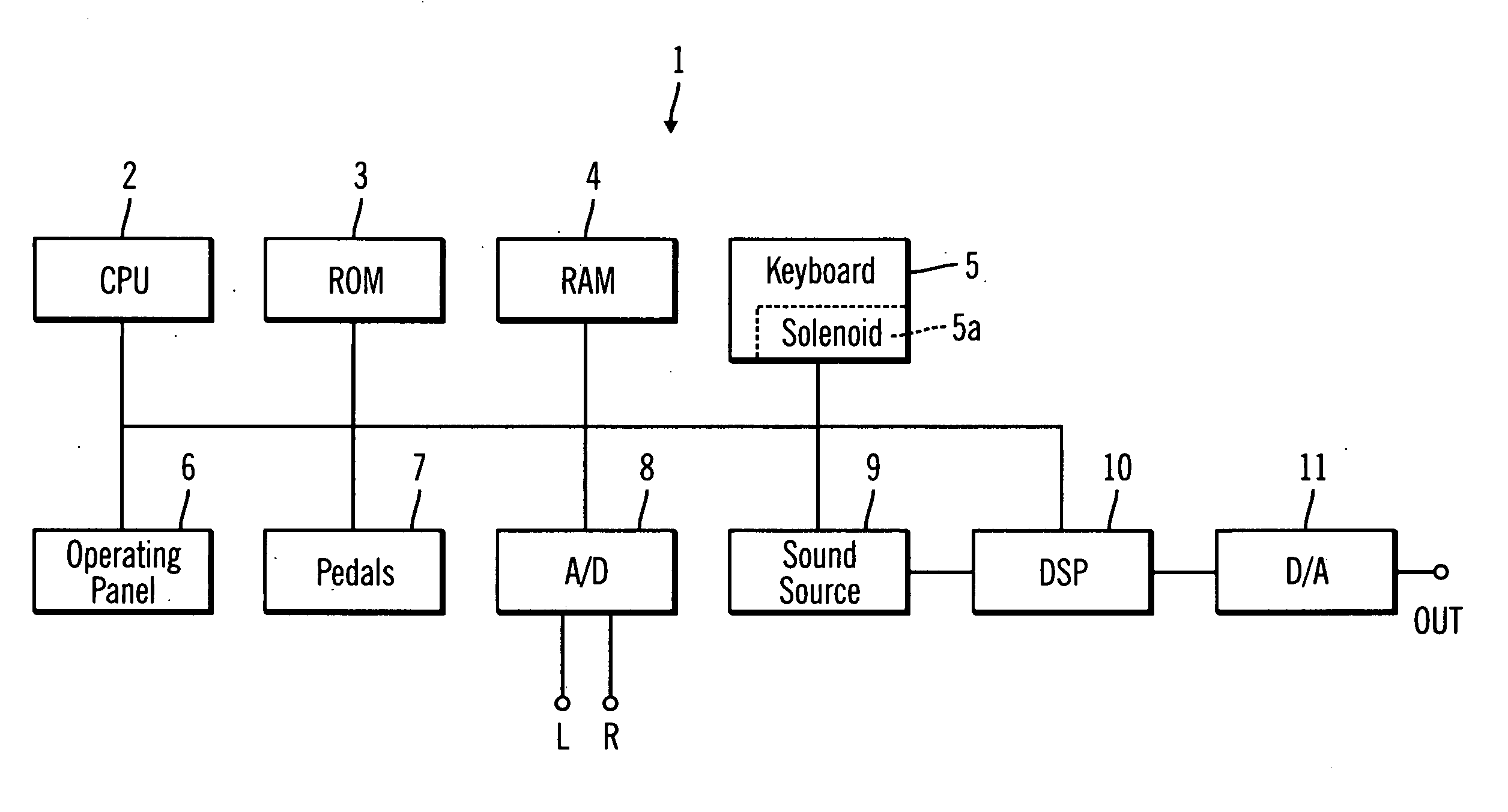
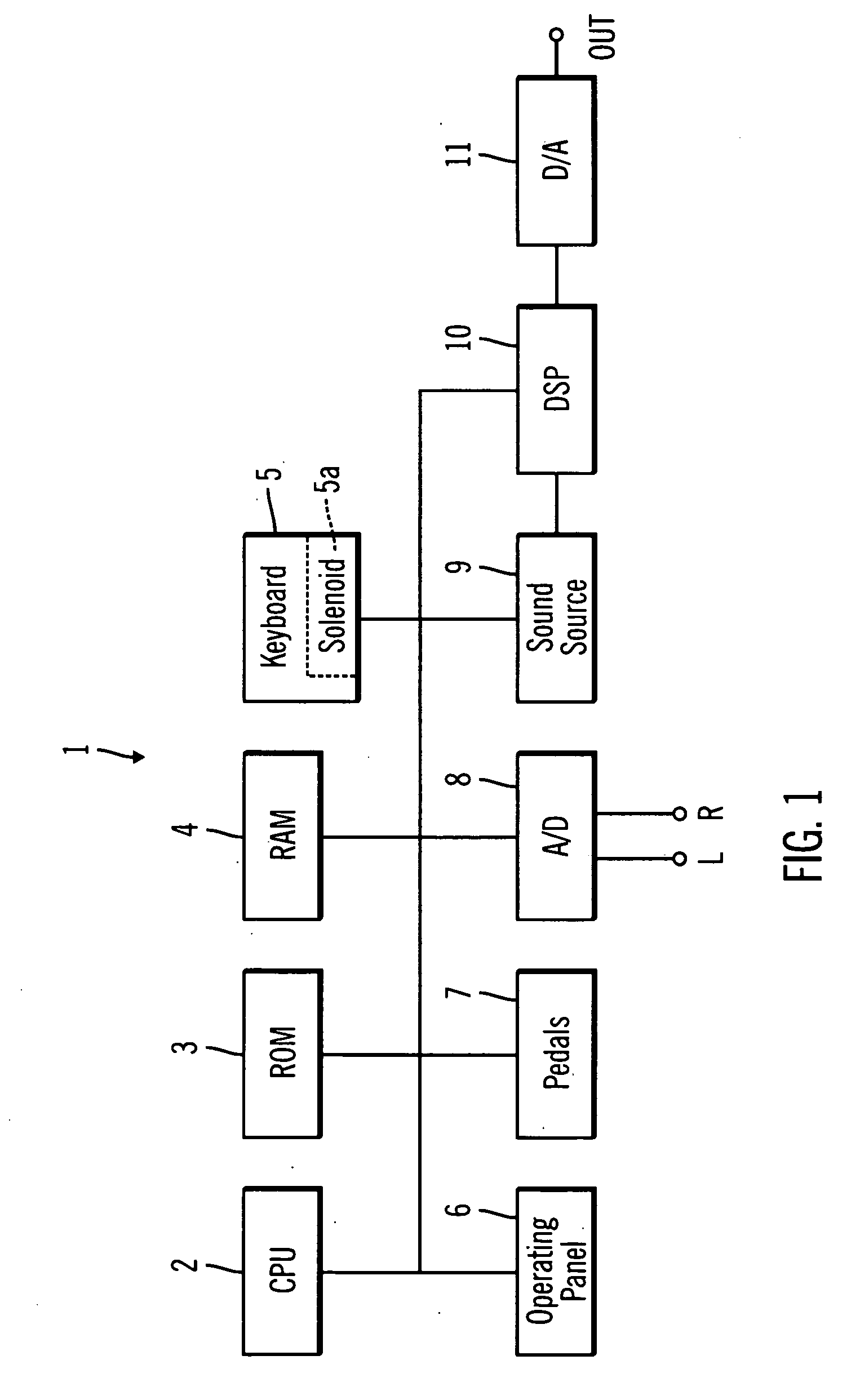
[0032] An explanation will be given regarding embodiments of the present invention while referring to the attached drawings. FIG. 1 is a block diagram that shows the electrical configuration of the electronic instrument 1, according to one embodiment of the present invention.

[0033] The electronic instrument 1 includes central processing unit (CPU) 2, read only memory (ROM) 3, random access memory (RAM) 4, keyboard 5, operating panel 6, pedals 7, analog to digital (A / D) converter 8, sound source 9 and digital signal processor (DSP) 10 all mutually interconnected by the bus line 50. The output of the DSP 10 is connected to a digital to analog (D / A) converter 11.

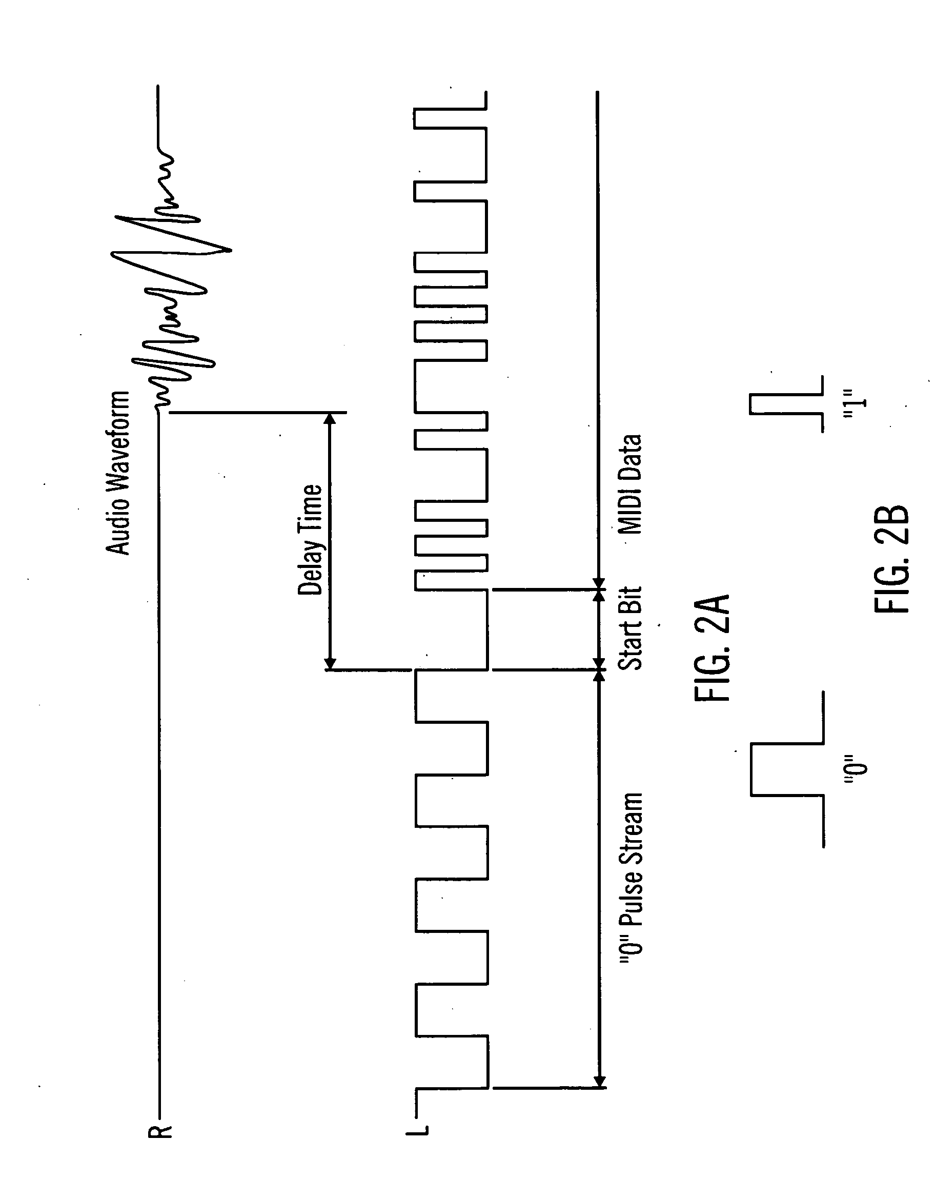
[0034] The CPU 2 is an arithmetic processing unit and the various types of control programs that are executed by the CPU 2 as well as the fixed value data referred to at the time of the execution are stored in the ROM 3. As for the control programs, these are programs that carry out processing such as the demodulation of an a...


PUM


Abstract

An electronic instrument includes an input device having a plurality of channels to each of which an audio signal is input. A demodulation device demodulates audio signals and converts the audio signals into digital signals that control the electronic instrument. The electronic instrument also includes a feeding device that feeds the digital signals to a sound source and a detection device that detects whether or not the audio signals in any of the plurality of channels are modulated by the digital signals. A controller controls the demodulation device, in cases where it has been detected that any of the audio signals are modulated by the digital signals, so as to demodulate the digital signals from the audio signals that have been input to the channels, such that another channel's audio signals that are not modulated by the digital signals are output to an audio output.

Description

CROSS-REFERENCE TO RELATED PATENT APPLICATIONS [0001] Japan Priority Application 2005-156587, filed May 30, 2005 including the specification, drawings, claims and abstract, is incorporated herein by reference in its entirety. BACKGROUND OF THE INVENTION [0002] 1. Field of the Invention [0003] Embodiments of the present invention relate to an electronic instrument and, in particular, embodiments to an electronic instrument in which an analog signal that is modulated by a digital signal is input, is demodulated, and fed to a sound source. [0004] 2. Description of the Related Art [0005] For some time electronic instruments have been known in which Musical Instrument Digital Interface (MIDI) data, which is data that conform to the MIDI standard, (a standard for performance data that carries out instructions such as the starting or stopping of the production of musical tone signals mutually between electronic instruments or between an electronic instrument and a personal computer), is in...

Claims


Application Information

Patent Timeline
Patent Type & Authority Applications(United States)
IPC IPC(8): H03M7/00
CPCG10H1/0066G10H1/363G10H2240/325G10H2210/295G10H1/368
Inventor MATSUOKA, KAZUHIKOKURAHASHI, KAZUO
Owner ROLAND CORP
Why Eureka
Try Eureka