Ink jet printing apparatus, ink jet print head, ink jet printing method, and method and program for setting print conditions

a printing apparatus and ink jet technology, applied in printing, other printing apparatus, etc., can solve the problems of low efficiency percentage, difficult machine, and inability to meet the requirements of printing, and achieve the effect of increasing the yield of the ink jet print head

Inactive Publication Date: 2006-12-07
CANON KK
View PDF15 Cites 24 Cited by
  • Summary
  • Abstract
  • Description
  • Claims
  • Application Information

AI Technical Summary

Benefits of technology

[0016] An object of the present invention is to provide an ink jet print head which, when a long ink jet print head is manufactured by arranging a plurality of chips, enables the suppression of a decrease in yield caused by the misalignment between the chips, the print head also being able to print high quality images, as well as an ink jet printing apparatus and method for printing images using this ink jet print head, a method for setting print conditions, and a program.
[0017] Another object of the present invention is to simplify image processing of an image corresponding to the joining portion between chips.
[0033] Since high-grade images can be printed even with an ink jet print head with misaligned chips, the yield of the ink jet print head can be increased. This enables the inexpensive provision of a long ink jet print head and an ink jet printing apparatus using this print head.

Problems solved by technology

However, for the full-multi type ink jet print head, it is difficult to machine, without any defects, all of a large number of ejection openings arranged across the width of a print area on the print medium and all elements (ink jet print elements) required to eject ink from the ejection openings.
It is difficult to machine, without any defects, all ink jet print elements corresponding to the large number of ejection openings.
Given that such print heads free from any defects can be manufactured, their efficiency percentage is very low and their manufacture costs are enormous.
However, with the joined head, image density is disadvantageously likely to be uneven in printed images corresponding to the joining portions among the plurality of chips.
However, even with the above measures for suppressing the occurrence of joining stripes, if the array of a plurality of chips becomes defective during a process of manufacturing print heads, suppressing the occurrence of joining strips is difficult.
Thus, if long print heads are manufactured by arranging a large number of chips, even when a defect occurs in only one of the joining portions among the chips, that print head as a whole must be rejected.
This reduces the yield of print heads.
Moreover, the improved precision of a device for arranging a plurality of chips increases manufacture costs.

Method used


Image

  • Ink jet printing apparatus, ink jet print head, ink jet printing method, and method and program for setting print conditions
  • Ink jet printing apparatus, ink jet print head, ink jet printing method, and method and program for setting print conditions
  • Ink jet printing apparatus, ink jet print head, ink jet printing method, and method and program for setting print conditions

Examples


first embodiment

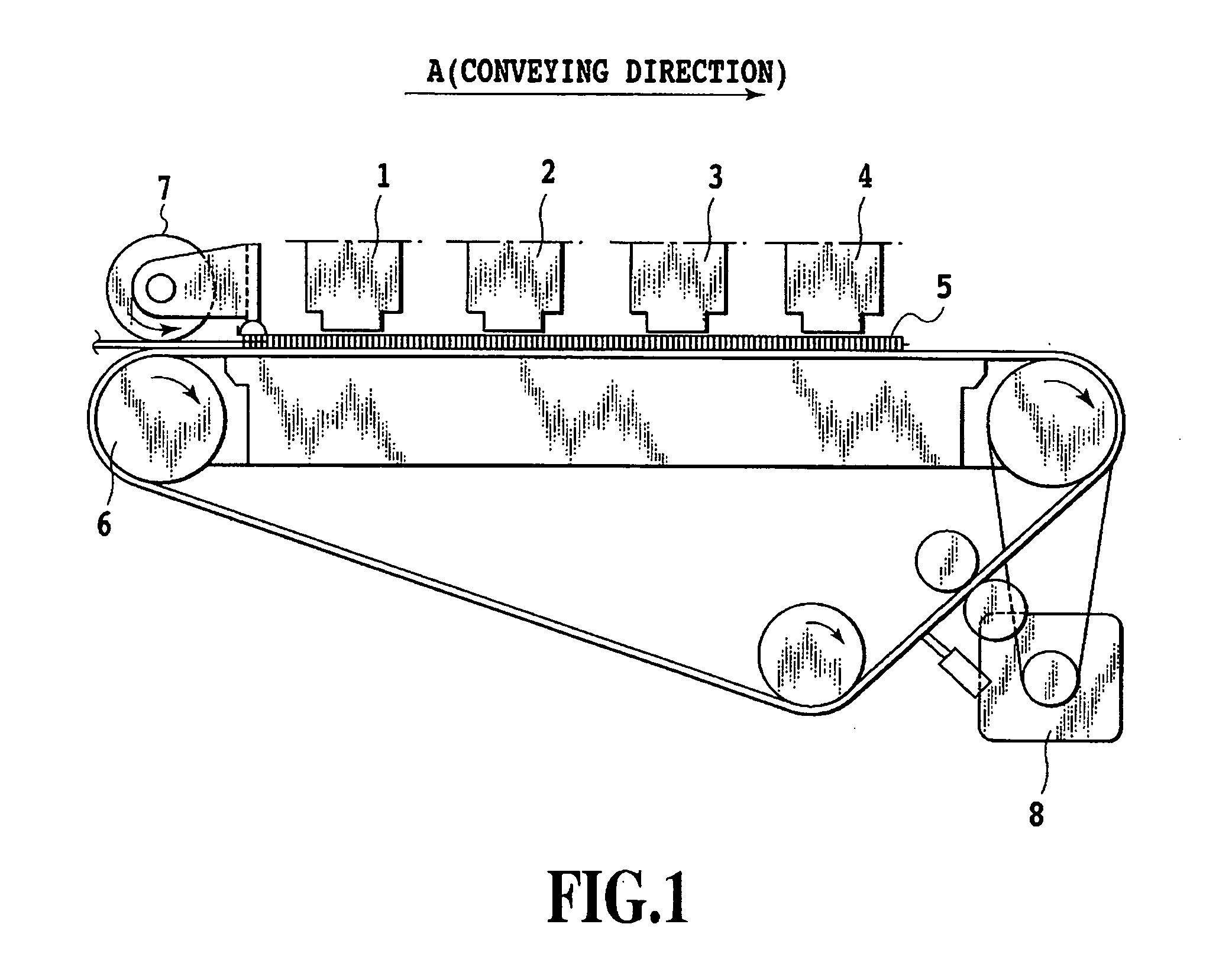
[0054]FIG. 1 is a side view illustrating the general configuration of an ink jet printing apparatus in accordance with a first embodiment of the present invention.

[0055] Long ink jet print heads 1, 2, 3, and 4 constitute a head unit. A plurality of ink ejection openings are arranged in each of the print heads to eject ink. The print heads 1, 2, 3, and 4 are long ink jet print heads that eject black (K), cyan (C), magenta (M), and yellow (Y) inks. Each of the print heads is supplied with ink through an ink supply tube (not shown). Moreover, control signals and the like are sent to each print head via a flexible cable (not shown). A print medium 5 such as ordinary paper, high-grade dedicated paper, an OHP sheet, glossy paper, a glossy film, or a postcard is sandwiched between a conveying roller 6 and a sheet pressing roller 7 and driven by a drive motor 8. The print medium 5 is thus fed in the direction of arrow A (conveying direction).

[0056] Liquid paths that are in communication w...

second embodiment

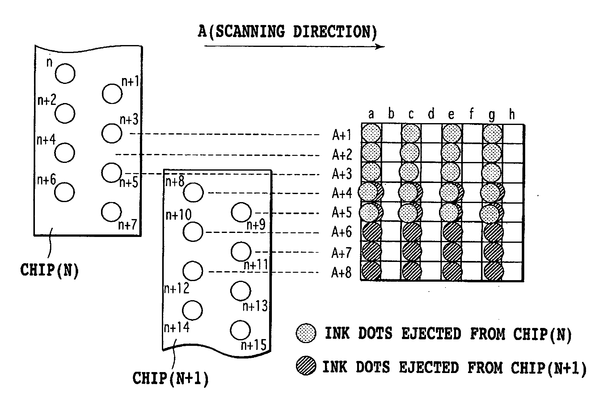
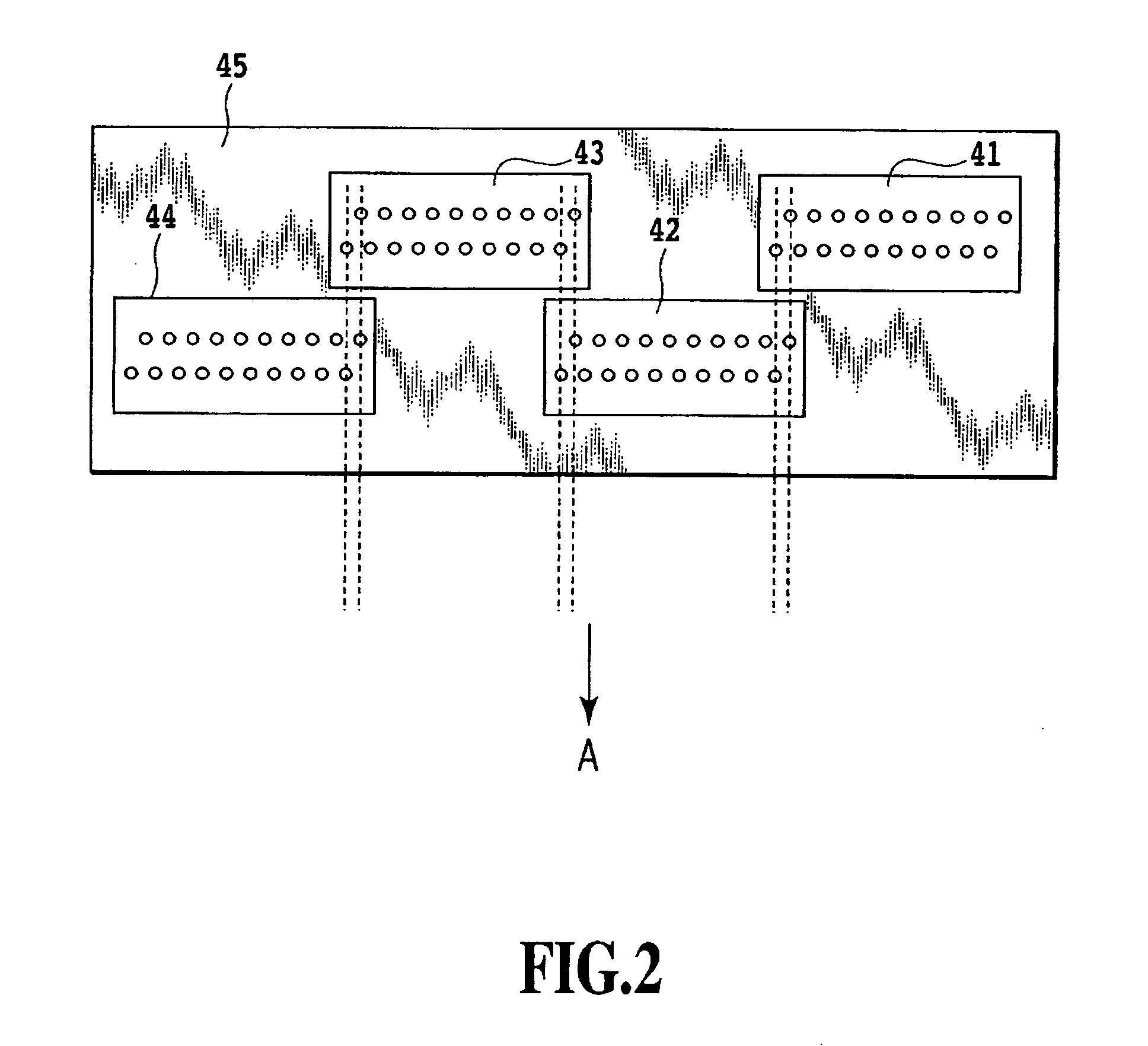
[0078]FIG. 13 shows an example of configuration of a full-multi type long print head used for a second embodiment of the present invention. In the present example, a print head includes a plurality of (in FIG. 13, four) short chips 51, 52, 53, and 54 each having four nozzle lines (L1, L2, L3, and L4). The chips 51, 52, 53, and 54 are staggered in the direction of the nozzle lines, thus constituting a long nozzle group unit 55. In each of the nozzle line groups L1 to L4, the pitch P between the nozzles is 600 dpi (about 42.4 μm). The nozzles in each of the nozzle line groups L1 to L4 are offset from the corresponding nozzles in the adjacent nozzle line group, by a P / 4 pitch (2,400 dpi). In each of the joining portions among the four chips 51 to 54, two nozzles in each of the nozzle line groups L1 to L4, that is, a total of eight nozzles in the nozzle line groups L1 to L4, overlap one another.

[0079] Alignment marks serving as reference positions are provided in the four corners of ea...


PUM


Abstract

In manufacturing a long ink jet print head in which a plurality of chips are arranged, the present invention can suppress a decrease in yield resulting from the inappropriate arrangement of the chips and enables high-quality images to be printed. To achieve this, the present invention prints an image corresponding to the joining portion between adjacent chips by using, as overlapping nozzles, those of the nozzles located in the joining portion which are selected on the basis of the amount of misalignment between chips.

Description

BACKGROUND OF THE INVENTION [0001] 1. Field of the Invention [0002] The present invention relates to a long ink jet print head in which a plurality of relatively short nozzle chips provided with nozzles are precisely arranged (what is called a joined head), an ink jet printing apparatus that prints images using this ink jet print head, an ink jet printing method, and a method and program for setting print conditions. [0003] 2. Description of the Related Art [0004] The following printing apparatuses are configured to print images (including characters and symbols) on print media such as sheets, thin plastic plates, or the like: those which are used for printers, copiers, and the like or which are used as composite electronic equipment including a computer, a word processor, or the like as well as output equipment such as a workstation. These printing apparatuses can be classified into an ink jet type, a wire dot type, and a laser beam type according to a printing system. [0005] Seria...

Claims


Application Information

Patent Timeline
Patent Type & Authority Applications(United States)
IPC IPC(8): B41J2/205
CPCB41J2/2135
Inventor UJI, AYAKOMURAYAMA, YASUSHI
Owner CANON KK
Why Eureka
Try Eureka