Imaging device and method of processing imaging result in imaging device

a technology of imaging device and image quality, which is applied in the direction of static indicating device, color signal processing circuit, instruments, etc., can solve the problems of inability to adjust image quality, grayscale correction and chroma correction problematically affecting practical use, and problematically deteriorating image quality, so as to prevent easy and flexible image correction, the effect of preventing the change of lightness

Active Publication Date: 2006-12-07
HANGZHOU HIKVISION DIGITAL TECH
View PDF8 Cites 50 Cited by
  • Summary
  • Abstract
  • Description
  • Claims
  • Application Information

AI Technical Summary

Benefits of technology

[0019] According to the first embodiment, only the lightness or the chroma can be corrected, which allows the chroma to be corrected with a change of the lightness being prevented. Furthermore, all the representative colors can be adjusted optimally so that the adjustment operations for the respective representative colors have no effect on each other. In addition, image quality can be corrected without using a computer or the like. These advantages allow image quality to be corre

Problems solved by technology

However, the processing for adjusting image quality through the grayscale correction and chroma correction problematically involves inadequacy in terms of practical use.
Specifically, when chroma correction is implemented by linear transformation on a color difference plane as described above, lightness is also changed, which problematically deteriorates image quality.
This problem is elicited by chroma enhancement accompanied by the corresponding lightness increase.
More specifically, although a change of the level of a color difference signal causes no change of a luminance signal, this level change of the color difference signal in the L*a*b* color system, which is a color system close to the perception of a human, problematically leads to a change of the lightness L*.
When the gain of a color difference signal is increased by the chroma correction, the lightness L* increases in an area with a high chroma and a low lightness, which spoils the three-dimensional appearance of the imaging result.
However, even this method cannot prevent a change of lightness completely.
In addition, there is another problem that the grayscale correction and chroma correction are processing for converting the entire color space, and therefore involve a difficulty in adjusting only a limited area of the color space.
Accordingly,

Method used


Image

  • Imaging device and method of processing imaging result in imaging device
  • Imaging device and method of processing imaging result in imaging device
  • Imaging device and method of processing imaging result in imaging device

Examples


first embodiment

1. Configuration of Embodiment

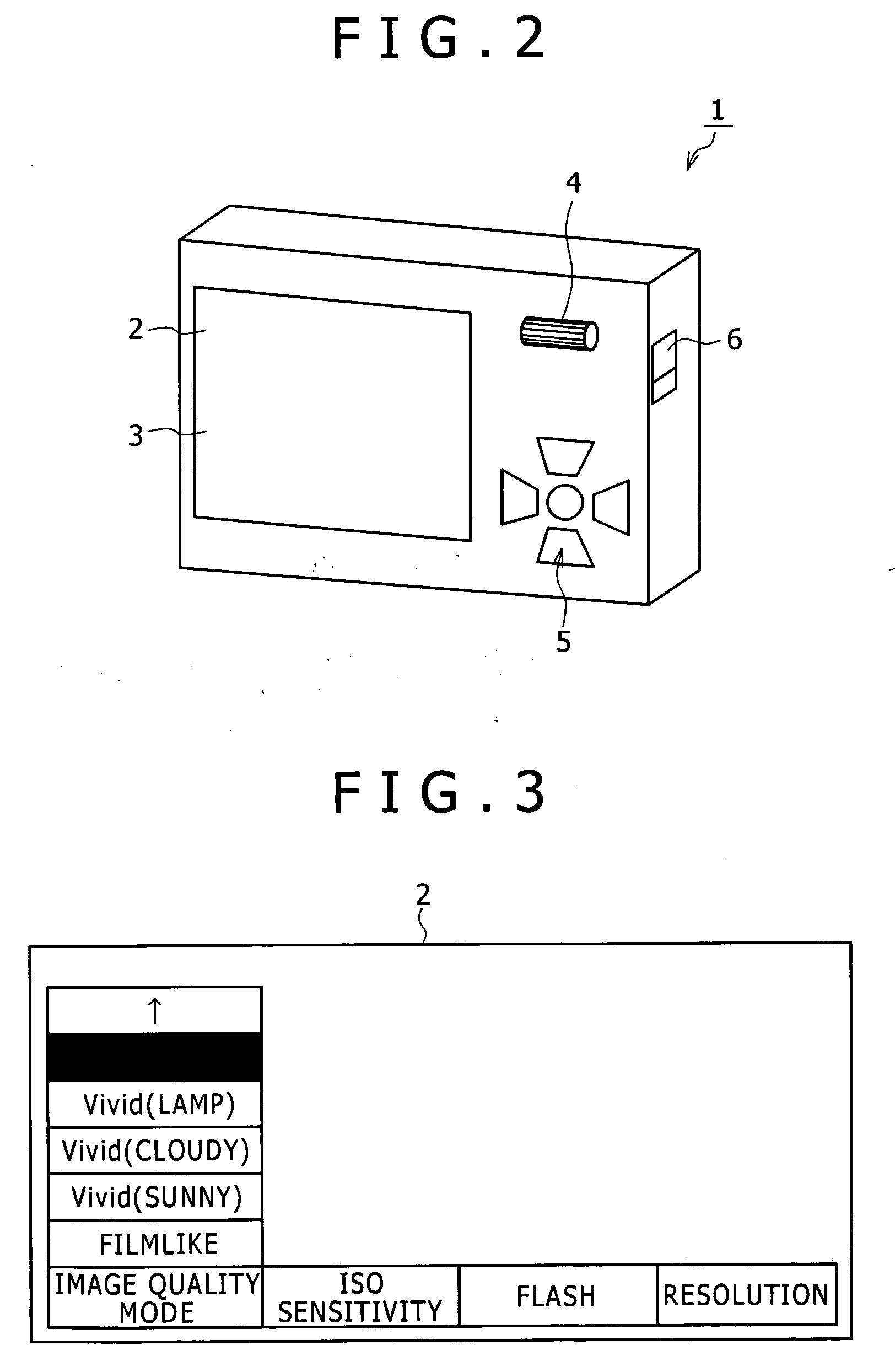
[0057]FIG. 2 is a perspective view illustrating an electronic still camera according to a first embodiment of the invention. The electronic still camera 1 is formed into a rectangular thin plate shape, and has a lens and so forth on the front face thereof. In addition, the electronic still camera 1 has a liquid crystal display 2 for monitoring an imaging result on its backside illustrated in the drawing. A touch panel 3 is provided on the display screen of the liquid crystal display 2. Thus, an item in a menu displayed on the liquid crystal display 2 can be selected through the operation of the touch panel 3. The electronic still camera 1 also has on its backside a rotary operating element 4 that can be pressed, and an operating element 5 for selecting a direction and making a decision. Furthermore, the electronic still camera 1 has a slide switch 6 on its side face. The operation of these operating elements 4 to 6 also permits the acceptance of operat...

second embodiment

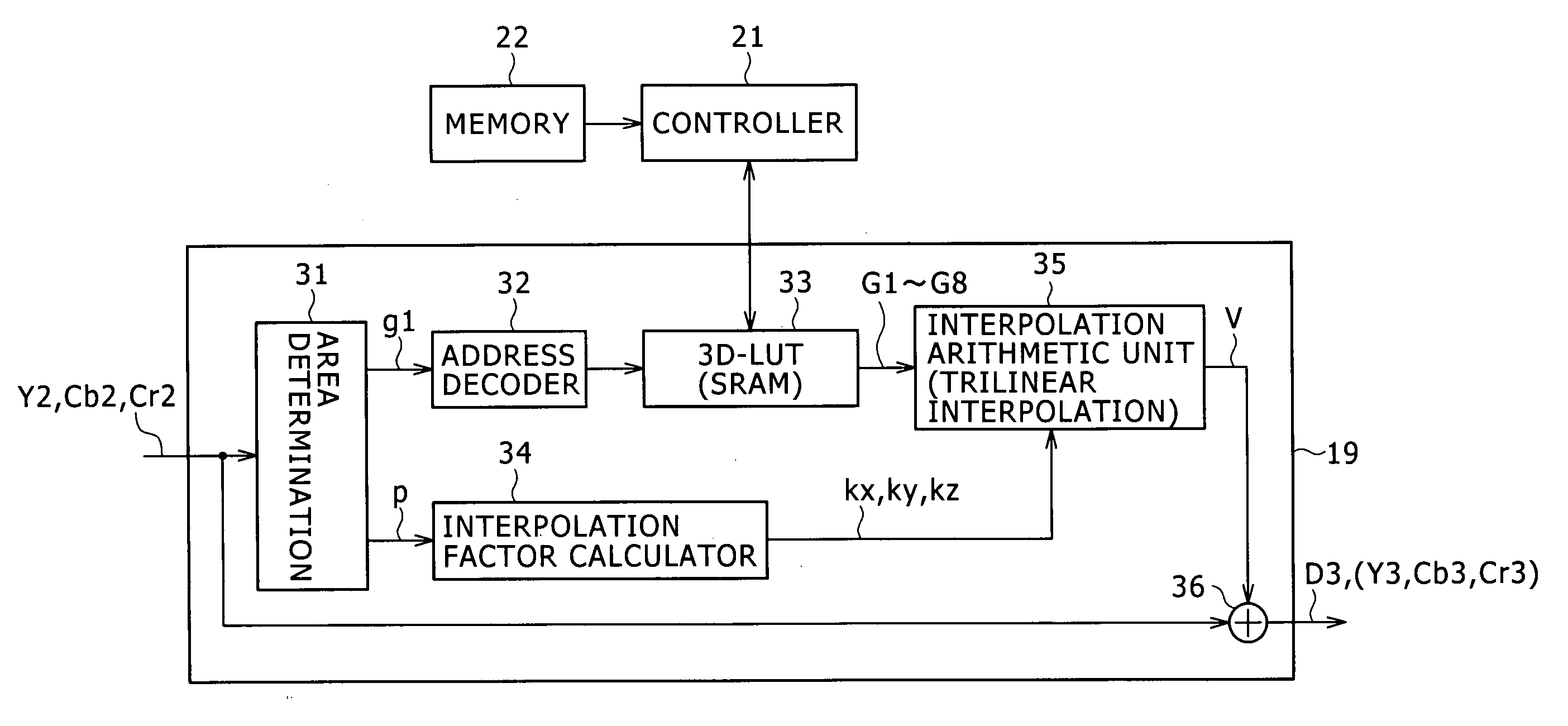
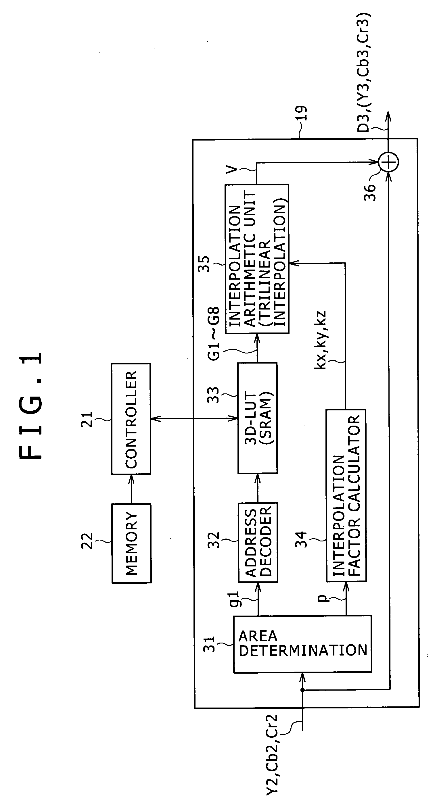
[0107]FIG. 11 is a plan view illustrating a color mode setting screen in an electronic still camera according to a second embodiment of the invention. The electronic still camera according to this embodiment accepts setting of image quality correction through this color mode setting screen, and sets correction data in a 3D-LUT. The second embodiment has the same configuration as that of the electronic still camera 1 of the first embodiment, except that a series of processing relating to the color mode setting is different. Therefore, the following description also employs the above-described configurations of FIGS. 1 and 4.

[0108] Displayed on this setting screen in the initial state is a menu including items such as image quality correction mode (color mode), ISO sensitivity, flash, and resolution similarly to the above description for the first embodiment (FIG. 3). Selecting from the menu leads to the indication of the corresponding sub menu. Specifically, when the item of image q...

third embodiment

[0117]FIG. 13 is a block diagram illustrating an electronic still camera 41 according to a third embodiment of the invention. In the electronic still camera 41, the same components as those in the electronic still camera of the first and second embodiments are given the same numerals, and overlapping description thereof will be omitted. The electronic still camera 41 automatically selects an image quality correction mode according to imaging conditions that can be detected at the time of imaging.

[0118] In the electronic still camera 41, the driving of a motor 43 moves a focus lens 42 in the optical axis direction, and thus the focus is adjusted so that an optical image is formed on the imaging plane of an imaging element 12.

[0119] A signal processor 44 serves as a configuration including the above-described components from the demosaic processor 13 to the gamma corrector 16 in the first embodiment. The signal processor 44 converts an imaging result obtained from the imaging elemen...


PUM


Abstract

The present invention relates to an imaging device and a method of processing an imaging result in an imaging device, and is applied to e.g. an electronic still camera to thereby allow the camera to correct image quality readily and flexibly with avoiding the deterioration of the image quality effectively. In the present invention, a three-dimensional look-up table is provided and an imaging result (Y2, Cb2, Cr2) is corrected by use of the three-dimensional look-up table.

Description

CROSS-REFERENCE TO RELATED APPLICATIONS [0001] The present application claims priority from Japanese Patent Application No. JP 2005-160841 filed on Jun. 1, 2005, the disclosure of which is hereby incorporated by reference herein. BACKGROUND OF THE INVENTION [0002] The present invention relates to an imaging device and a method of processing an imaging result in an imaging device, and can be applied to an electronic still camera for example. The invention employs a three-dimensional look-up table and corrects an imaging result by use of the three-dimensional look-up table, to thereby enable image quality to be readily and flexibly corrected, with the deterioration of the image quality being avoided effectively. [0003] Conventionally, there has been provided an electronic still camera that allows image quality to be variously set according to color mode selection, and thus can offer wide compatibility with imaging environments, user's preferences, etc. [0004] Specifically, in this kin...

Claims


Application Information

Patent Timeline
IPC IPC(8): G03F3/08
CPCH04N9/735H04N23/88H04N9/64
Inventor WAKAZONO, MASAFUMIHAYAKAWA, HIROFUMIISHIGAMI, KOICHIROMIZUKURA, TAKAMIKATOH, NAOYAOKADA, MIYUKI
Owner HANGZHOU HIKVISION DIGITAL TECH
Why Eureka
Try Eureka