
Video rectractor

a rectractor and video technology, applied in the field of rectractors, can solve the problems of limiting the useful life of the rectractor, increasing the overall cost of providing the system to health care providers, and the system is out of service, so as to prevent inadvertent contamination of the patient, facilitate viewing, and operate effectively

Active Publication Date: 2006-12-07
VERATHON MEDICAL CANADA ULC
View PDF26 Cites 108 Cited by
  • Summary
  • Abstract
  • Description
  • Claims
  • Application Information

AI Technical Summary

Benefits of technology

[0010] The blade portion is either reusable, in which case only it needs to be sterilized between uses, or the blade portion is disposable, thereby further preventing inadvertent contamination of the patient. In one disclosed embodiment, the video system can be detachably secured to a variety of different shaped blade portions, thereby allowing the retractor, with its single video system, to operate effectively as a laryngoscope, anoscope, colposcope, and the like.
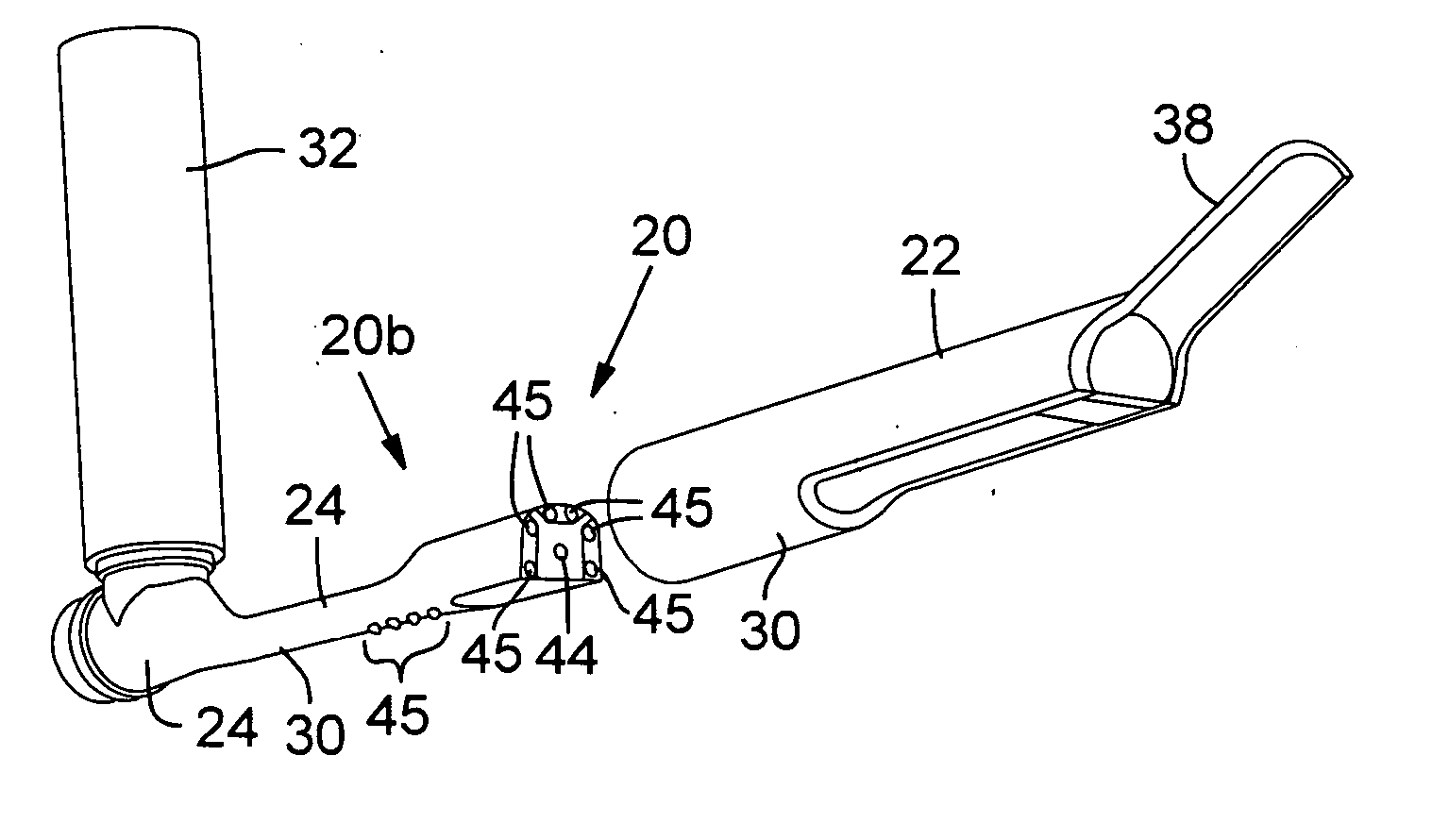
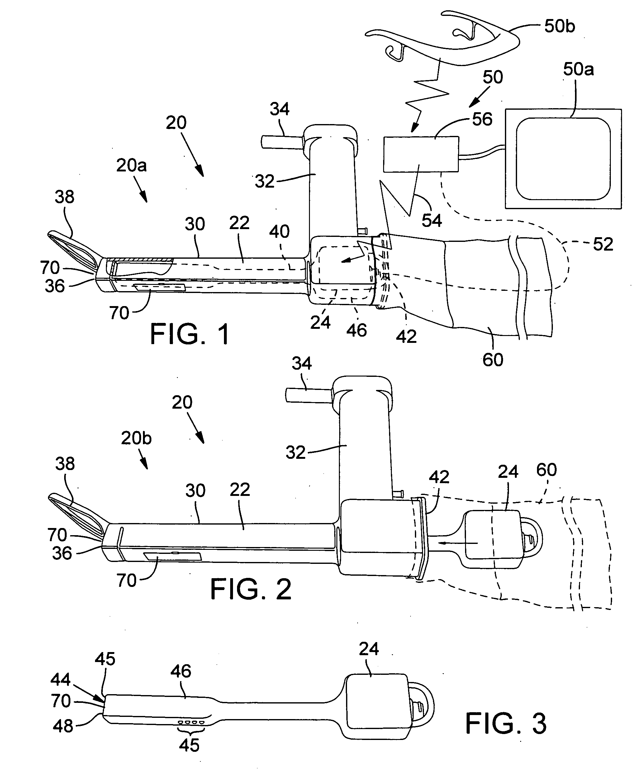
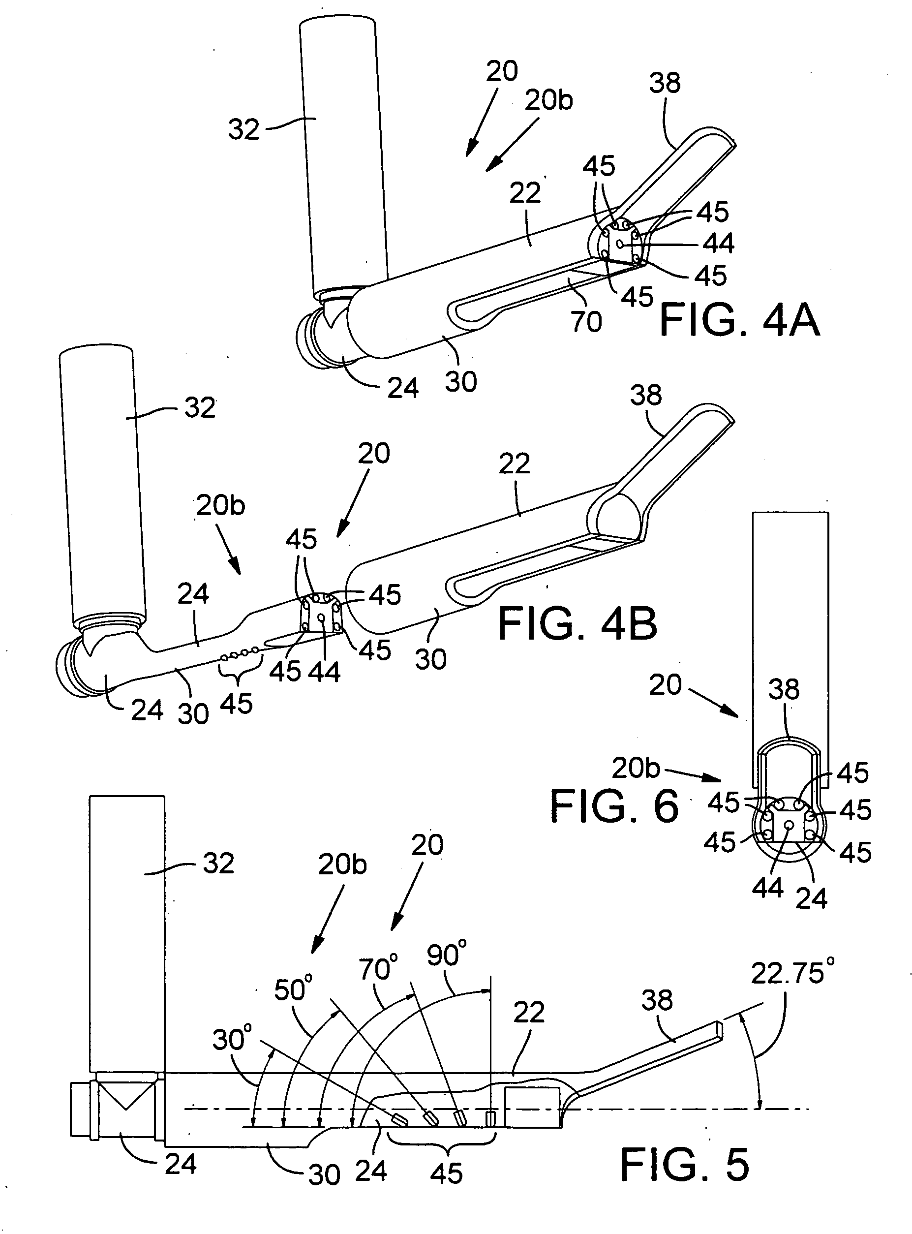
[0011] In one disclosed embodiment, the video system has a viewing device, which is preferably a Charged Coupled Device (“CCD”) or Complementary Metal Oxide Semiconductor (“CMOS”) camera positioned near the base end of a lifter portion of the blade portion, and aligned to provide a perspective view toward the distal end of the lifter. Lights, which are preferably Light Emitting Diode (“LED”) units, are positioned around the camera and directed toward the distal end of the lifter to facilitate viewing. A transparent protective sheathing, such as clear plastic or the like, is preferably provided on the detachable blade portion over the camera lens and lights to seal the video system within the retractor, thereby preventing the need for the video system to be sterilized between uses.

Problems solved by technology

Over time, these procedures can tend to prematurely deteriorate these components thereby limiting their useful lives.
Accordingly, despite the benefits associated with providing video and / or lighted retractors, the high number of cameras, lighting systems, their related electronic systems, and their related increased costs associated with maintaining them, significantly increases the overall costs of providing these systems to health care providers.
In addition, the camera system is out of service during cleaning cycles, which may impact its usefulness should an emergency need arise during the cleaning cycle.

Method used


Image

  • Video rectractor
  • Video rectractor
  • Video rectractor

Examples


Embodiment Construction

[0028] A retractor 20 having a blade portion 22 detachably secured to a video system 24 sealed therein is shown in FIGS. 1-12. In particular, FIGS. 1-3, 7A, 7B and 9 show a first preferred retractor embodiment 20a, FIGS. 4-7 show a second preferred retractor embodiment 20b, and FIGS. 10-12 show a third preferred retractor embodiment 20c. Alternative possible features are shown in FIG. 8. In order to avoid unnecessary repetition, common elements between these three embodiments 20a-c are like numbered.

A. First Preferred Embodiment

[0029] With particular reference to FIGS. 1-3, a first preferred retractor embodiment 20a is disclosed. The blade portion 22 has an elongated arm 30 with integrally attached handle 32. The blade portion 22 is preferably a monolithic structure formed with a material that can withstand repeated sterilization such as metal, rigid plastic, or the like. If desired, a rigid mounting pin 34 is also operably secured to the blade portion 22, preferably at the handle...


PUM


Abstract

A retractor with a video system that has a blade portion detachably secured thereto is disclosed. In one embodiment, the video system is sealed within the retractor during use so that it need not be sterilized between uses. The blade portion is either reusable, in which case only it needs to be sterilized between uses, or the blade portion is disposable, thereby further preventing inadvertent contamination of the patient. The video system can be detachably secured to a variety of different shaped blade portions, thereby allowing the retractor, with its single video system, to operate effectively as a straight or curved blade laryngoscope, anoscope, colposcope, and the like.

Description

REFERENCE TO RELATED APPLICATIONS [0001] This application claims priority to U.S. Provisional Application No. 60 / 666,842, filed on Apr. 1, 2005.FIELD OF THE INVENTION [0002] This invention relates to retractors used in the medical profession to permit controlled access and assist visibility during medical procedures and the like. BACKGROUND [0003] Retractors are probes used during medical procedures to provide the health care provider with controlled access to the patient and to assist with visibility of the area being treated. In general, a retractor has a control arm or blade portion that extends from a handle or base portion. The control arm or blade operably engages the area being treated, while the handle or base is used to position the control arm or blade as needed. The retractor can be hand-held by a health care provider or mounted to an examination table, operating table, or the like. [0004] The shape of the retractor's blade portion often defines and limits its use. For ex...

Claims


Application Information

Patent Timeline
IPC IPC(8): A61B1/32A61B1/267
CPCA61B1/00142A61B1/05A61B1/0676A61B1/31A61B1/267A61B1/303A61B1/0684A61B1/0625
Inventor PACEY, JOHN A.
Owner VERATHON MEDICAL CANADA ULC
Learn More