

Endoscopic surgical instrument
a surgical instrument and endoscope technology, applied in the field of endoscope surgical instruments, can solve the problems of inconvenience caused by needle holder treatment, limited range of use of needle holder, and danger of tissue damage, so as to simplify surgery operation, shorten surgery, and connect the suture thread more simply
- Summary
- Abstract
- Description
- Claims
- Application Information
AI Technical Summary
Benefits of technology
Problems solved by technology
Method used
Image

Examples
first embodiment
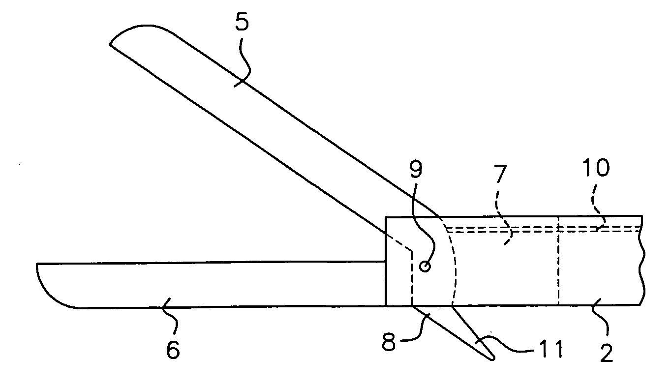
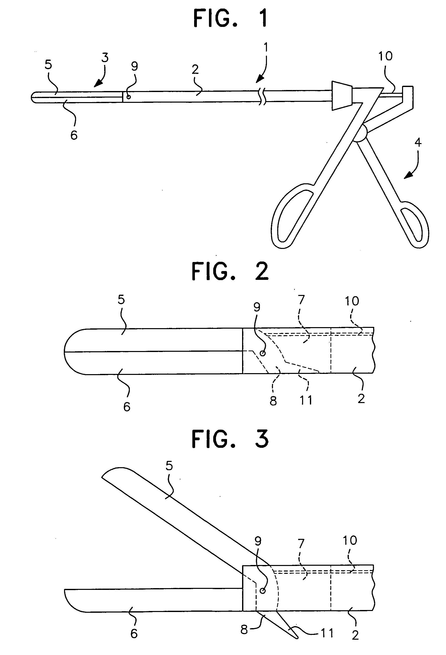
[0032] Next, an embodiment of an endoscopic surgical instrument according to the present invention will be described taking the case that a thread cutting function is not provided with reference to FIGS. 1 to 5. In the drawings, a reference numeral 1 denotes an endoscopic surgical instrument. A needle holding part 3 is disposed at its front end across a tubular shaft 2 that is an insertion part and an operation handle 4 is disposed at hand.
[0033] The tubular shaft 2 is configured by a movable jaw 5 an a fixed jaw 6, and on a contact face of the movable jaw 5 and the tubular shaft 6, a concave-convex groove for holding the needle or the like is formed, respectively. Then, the fixed jaw 6 is fixed to the tubular shaft 2. Further, the fixed jaw 6 may be integrated with the fixed jaw 6 functionally, or they may be integrated physically. In other words, the fixed jaw 6 may function as the needle holding part 2 with respect to the movable jaw 5.
[0034] On the center part of the front sid...
second embodiment
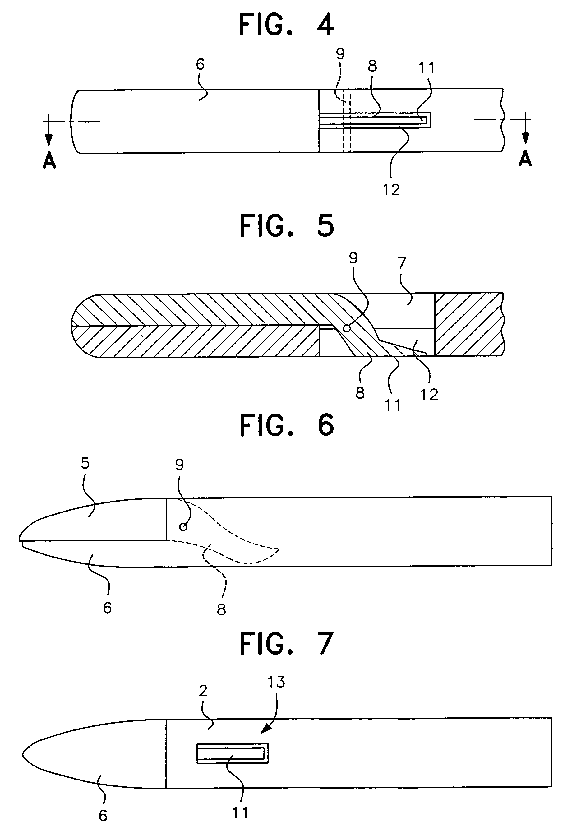
[0038] Next, another embodiment of the endoscopic surgical instrument according to the present invention will be described taking the case of having the thread cutting function with reference to FIGS. 6 to 9. Except for the thread cutting function, the second embodiment is the same as the first embodiment, so that the different points will be only explained below.
[0039] A reference numeral 13 denotes a scissors having the thread cutting function depending on the tubular shaft 2 and the thread locking part 11 of the movable jaw 5. A blade face is formed respectively at the part where the thread locking part 11 of the movable jaw 5 and the tubular shaft 2 can slidably move. When the movable jaw 5 is closed, the thread can be cut between the thread locking part 11 and the tubular shaft. According to the present embodiment, differently from the first embodiment, the thread pulling out gap 12 is not provided between the tubular shaft 2 and the thread locking part 11.
[0040] Next, a meth...
PUM
 Abstract
Description
Claims
Application Information