
Article transport facility and a method of operating the facility

Active Publication Date: 2006-12-07
DAIFUKU CO LTD
View PDF9 Cites 20 Cited by
  • Summary
  • Abstract
  • Description
  • Claims
  • Application Information

AI Technical Summary

Benefits of technology

[0010] This invention has been made having regard to the prior at noted above, and its object is to provide an article transport facility which can move a plurality of mobile bodies for article transport efficiently, while attaining a simplified construction.

Problems solved by technology

Thus, the above conventional article transport facility, when moving the plurality of mobile bodies for article transport, does not permit the distance between the two mobile bodies adjoining longitudinally of the track to become less than the predetermined distance.
In this case, there is a possibility that the plurality of mobile bodies cannot move efficiently for article transport.
Therefore, the mobile bodies cannot be moved efficiently for article transport.
When an abnormality occurs with one of the mobile bodies, the abnormal mobile body cannot be moved by using the normal mobile body.
The rearward mobile body is moved only after the two mobile bodies become spaced apart by the predetermined distance, In this way, it is necessary to perform a operation for making the distance between the two mobile bodies at least the predetermined distance, Thus, the plurality of mobile bodies cannot be moved efficiently for article transport.
This operation is time-consuming, and consequently the plurality of mobile bodies cannot be moved efficiently for article transport.
In this case, the coupling device with the actuator must newly be provided for the mobile bodies, resulting in a complicated construction.

Method used


Image

  • Article transport facility and a method of operating the facility
  • Article transport facility and a method of operating the facility
  • Article transport facility and a method of operating the facility

Examples


first embodiment

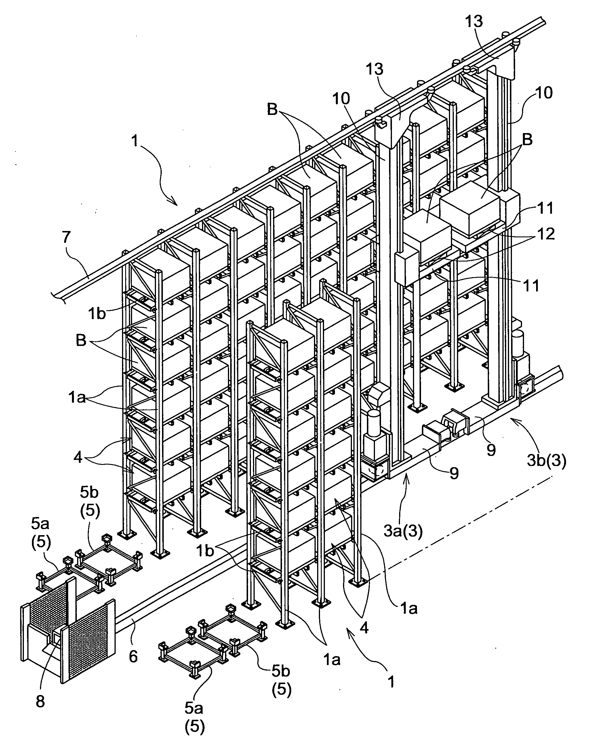
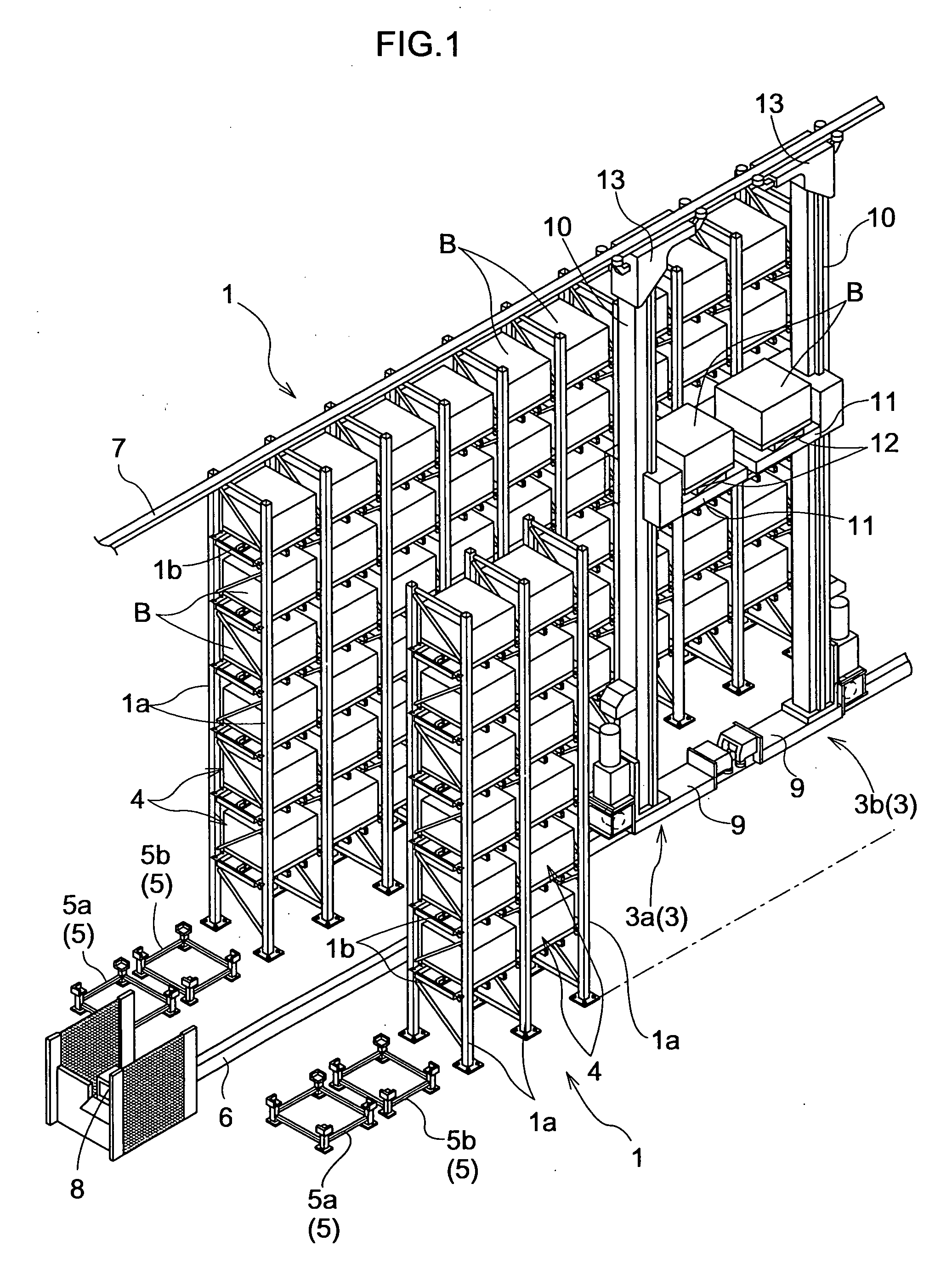
[0041] An article storage facility in a first embodiment, as shown in FIG. 1, includes two article storage racks 1 installed with a space in between, and with opposed open front planes thereof for loading and unloading articles B, and stacker cranes 3 as article transporting mobile bodies automatically movable forward and backward along a running passage 2 formed between the two article storage racks 1.

[0042] Each article storage rack 1 has pairs of front and rear struts 1a erected at interval in the direction of width of the rack (horizontal direction). Each pair of front and rear struts 1a has a plurality of supports 1b extending in the direction of width of the rack and arranged at intervals in the vertical direction.

[0043] Each article storage rack 1 has a plurality of storage units 4 arranged vertically and in the direction of width of the rack. Each storage unit 4 stores an article B as placed on the support 1b.

[0044] The storage units 4 have substantially the same width in ...

second embodiment

[0140] Next, this invention will be described with reference to FIG. 16 et seq. This embodiment relates to coping with an abnormality occurring with one of the mobile bodies. While a plurality of embodiments are described herein, a combination of the characteristic features of one embodiment different from the characteristic features of the other embodiments is also included in the scope of this invention in the absence of a conflict. In the following description, like reference numbers will be affixed to like components which are the same as in the foregoing embodiment, and will not be described again.

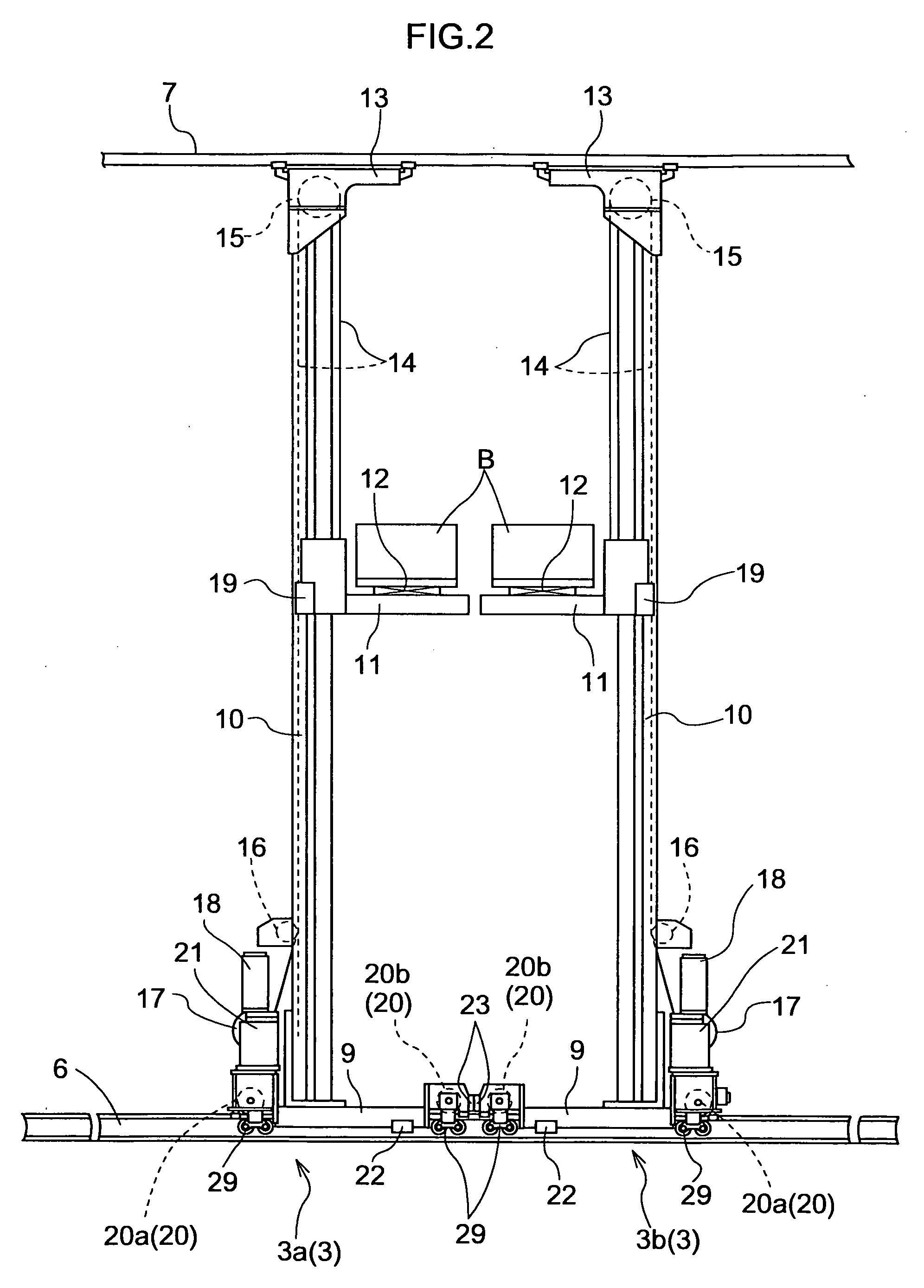
[0141] In the second embodiment, as shown in FIG. 16, the lifting electric motor 18 and drum 17 are supported in a position farther away from the vertical mast 10 than the running electric motor 21. In this embodiment, each stacker crane has a control device as described in detail hereinafter. In this embodiment, a chain 14 is used instead of the wire 14, and a guide sprocket 15 inste...


PUM


Abstract

An article transport facility includes a plurality of mobile bodies movable along a single track for transporting articles, and a control device for controlling movement of the mobile bodies. The control device is capable of executing a joint moving operation for moving the mobile bodies in combination. In this operation, a first mobile body which is one of the mobile bodies pushes a second mobile body which is another of the mobile bodies.

Description

BACKGROUND OF THE INVENTION [0001] This invention relates to an article transport facility, and more particularly to an article transport facility having a plurality of mobile bodies movable forward and backward along a single track for transporting articles, and a control means for controlling operation of the mobile bodies. The invention relates also to a method of operating the facility. [0002] The above article transport facility transports articles by reciprocal movement of each of the mobile bodies along a track. This facility realizes improved transport capacity by transporting articles with the plurality of mobile bodies. [0003] A conventional article transport facility as noted above has two mobile bodies for moving forward and backward along the track. The control means is provided for controlling operation of the two mobile bodies to move and transport articles as separated from each other at least by a predetermined distance (see Japanese Patent Publication (Unexamined) ...

Claims


Application Information

Patent Timeline
IPC IPC(8): G06F7/00
CPCB65G1/0407B65G1/0492B65G1/0421B66F9/07
Inventor TSUJIMOTO, KAZUSHIUEDA, YUICHITSUKAMOTO, KUNIHIRO
Owner DAIFUKU CO LTD
Learn More