Discrimination apparatus

Inactive Publication Date: 2006-12-07
CANON KK
View PDF23 Cites 17 Cited by
  • Summary
  • Abstract
  • Description
  • Claims
  • Application Information

AI Technical Summary

Benefits of technology

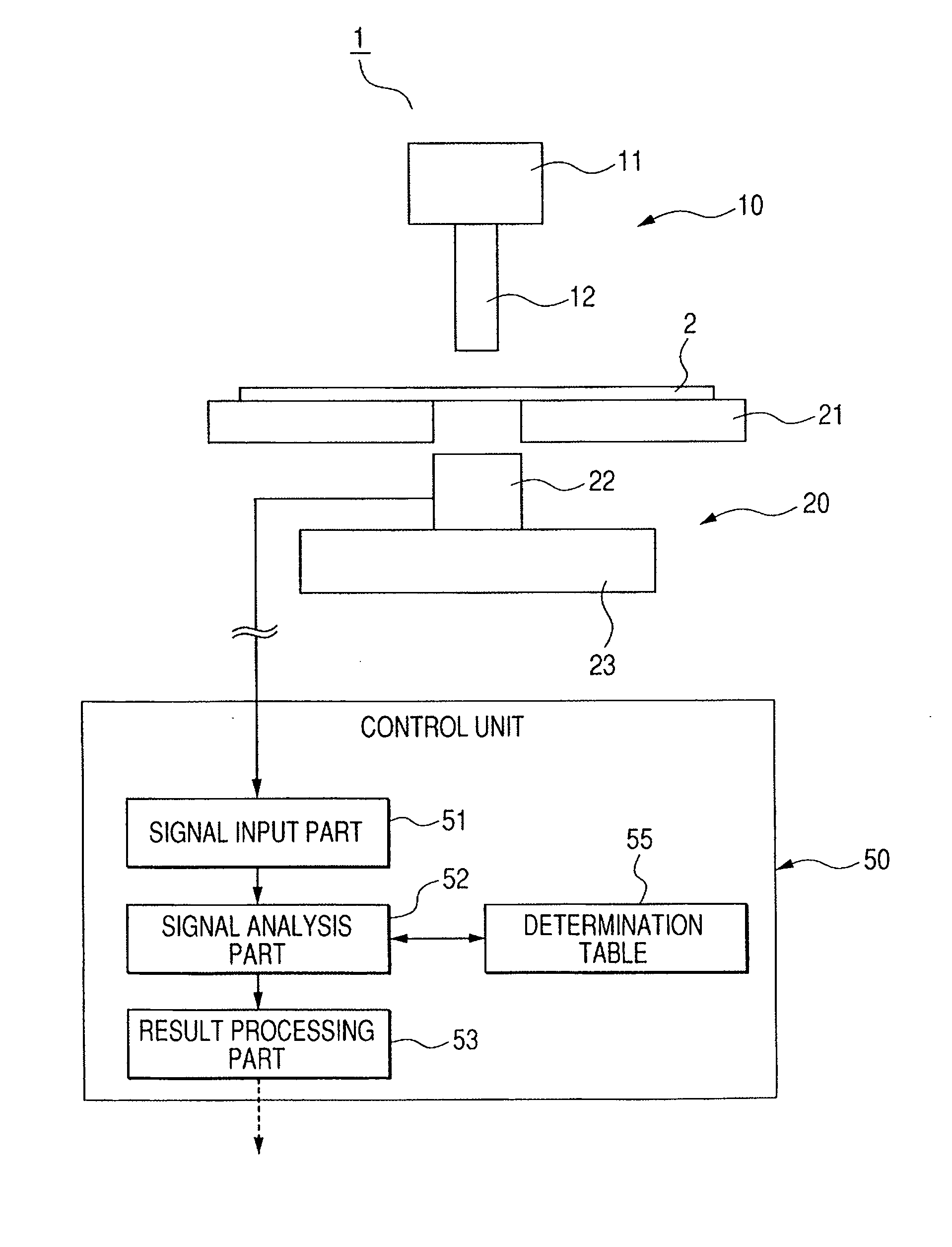
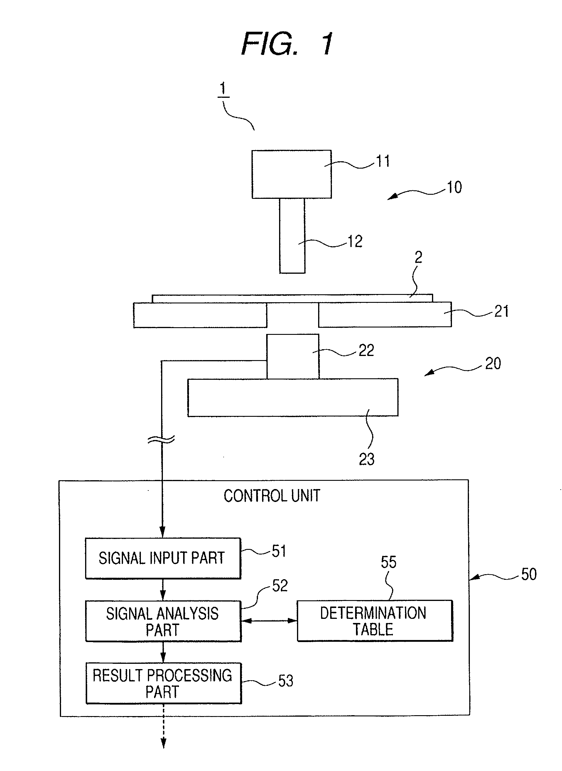
[0010] To solve the above-mentioned problems, according to one aspect of the present invention, a discrimination apparatus includes: an impact-applying unit for applying an impact to an object to be discriminated; a signal output unit for outputting a signal corresponding to an impact applied by the impact-applying unit; a discrimination unit for discriminating the object to be discriminated on a basis of the signal from the signal output unit; and a pressure-receiving position correction member including a pressure-receiving part for receiving an impact force applied by the impact-applying unit, and an action part for actin

Problems solved by technology

That is, a difference occurs in the output signal, which causes a lack of precision.
However, the impact application means does not always accurately apply the impact to the same position due to, for example, degradation with elapse of time or the error of respective components.
Also, there is a fear that the position at which the force is applied to the signal output means is different due to a shape or a located position of the object to be discriminated.
Also, in particular, in a case where the impact applic

Method used


Image

  • Discrimination apparatus
  • Discrimination apparatus
  • Discrimination apparatus

Examples


embodiment 1

[0027] Now, a description will be given of Embodiment 1 according to the present invention with reference to FIGS. 3 to 5B. FIG. 3 is a structural diagram showing an impact application unit according to Embodiment 1, FIG. 4 is a structural diagram showing an impact force detection unit according to Embodiment 1, and FIGS. 5A and 5B are diagrams showing relationships between an impact-applying position and a generated voltage. FIG. 5A is a diagram in the case of directly applying an impact force to a piezoelectric element as a mechano-electrical transducer, and FIG. 5B is a diagram in the case of applying the impact force to the piezoelectric element through a pressure-receiving position correction member.

[0028] As shown in FIG. 3, a driving device 11 of an impact application unit 101 according to this embodiment is equipped with a motor 13, and a driving shaft 14 that is rotatably driven by the motor 13 is rotatably supported by a main body 19. Also, the driving shaft 14 is fixed w...

example 1

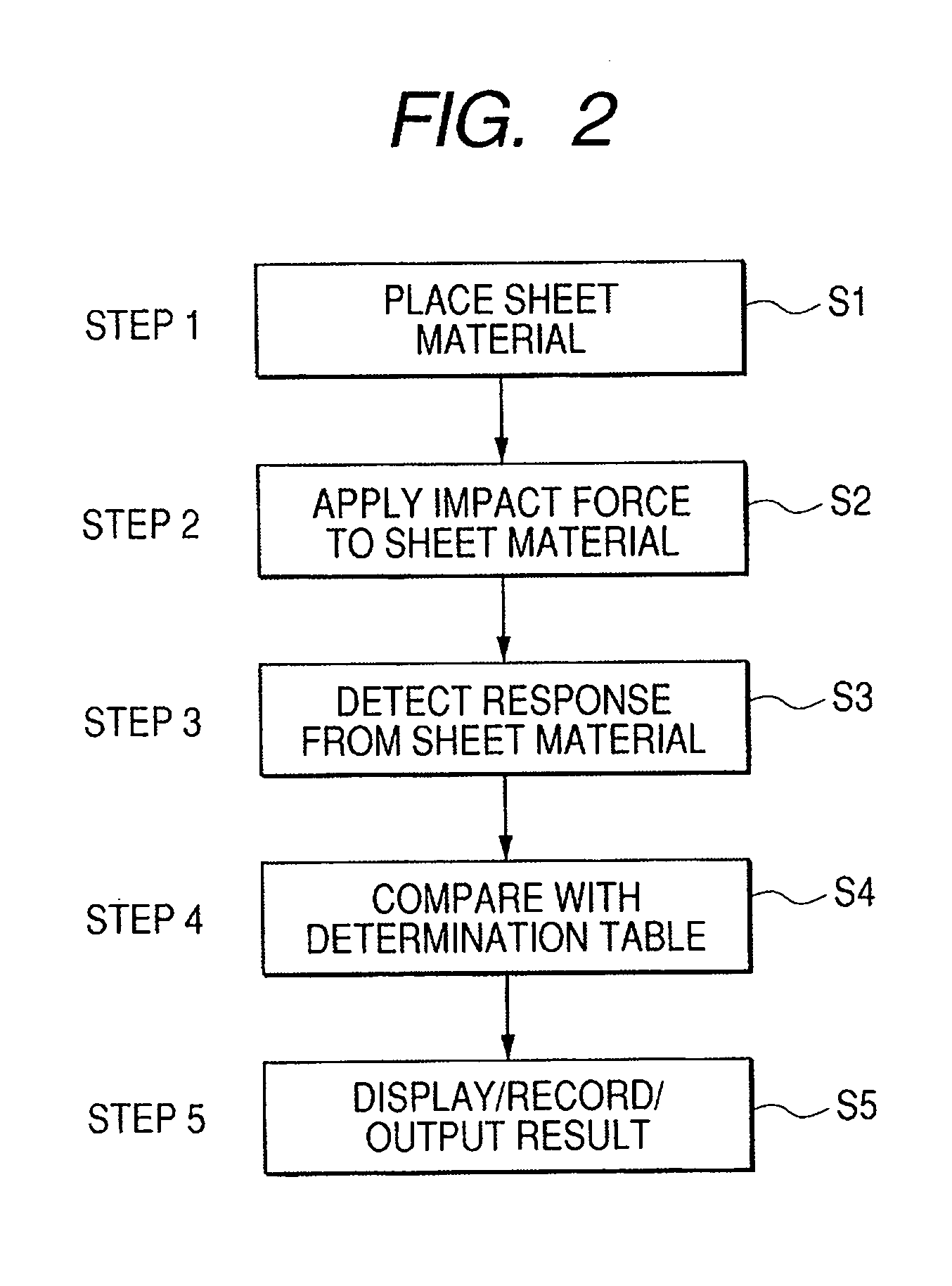
[0043] Subsequently, Example 1 according to the present invention will be described with reference to FIGS. 3 to 7. FIG. 6 is a timing chart showing an example of the generated voltage of the piezoelectric element at the time of applying an impact, and FIG. 7 is a diagram showing an example of the determination table.

[0044] As shown in a structure of FIG. 4, the impact force detection unit 201 according to the present invention is composed of a piezoelectric element 25, the viscoelectric members 26 and 28 that interpose the piezoelectric element 25 therebetween, and the pressure-receiving position correction member 27 embedded in the viscoelastic member 26. The overall shape of the impact force detection unit 20, is 5 mm in width, 10 mm in length, and 5 mm in height. The pressure-receiving position correction member 27 is attached to the center portion of the piezoelectric element 25 that detects the signal. According to this example, the pressure-receiving position correction memb...

embodiment 2

[0049] Subsequently, a description will be given of Embodiment 2 according the present invention, which partially modifies Embodiment 1. FIG. 8 is a structural diagram showing a discrimination apparatus according to Embodiment 2. In Embodiment 2, the same parts as those in Embodiment 1 are denoted by the same reference symbols, and their description will be omitted.

[0050] As shown in FIG. 8, a discrimination apparatus 1 according to Embodiment 2 is composed of an impact-applying unit 102 and an impact force detection unit 202. The impact applying unit 102 has no pressing members 16 and 17 (refer to FIG. 3) as compared with the impact-applying part 10, of Embodiment 1. Also, the discrimination apparatus 1 has no spring 18B for urging the impact-applying member 12, that is, applies the impact force by lifting the impact-applying member 12 using the cam 15 and then naturally dropping the impact-applying member 12.

[0051] A signal output part 22 of the impact force detection unit 202 i...


PUM


Abstract

Provided is a discrimination apparatus including: an impact application unit for applying an impact to an object to be discriminated; a signal output unit for outputting a signal corresponding to an impact applied by the impact application unit; a discrimination unit for discriminating the object to be discriminated on basis of the signal from the signal output unit; and a pressure-receiving position correction member having a pressure-receiving part for receiving an impact force applied by the impact application unit, and an action part for acting the impact force received at the pressure-receiving part on a predetermined site of the signal output unit.

Description

BACKGROUND OF THE INVENTION [0001] 1. Field of the Invention [0002] The present invention relates to a discrimination apparatus for applying an impact to an object to be discriminated to discriminate the object to be discriminated on the basis of an output signal corresponding to the impact application. [0003] 2. Related Background Art [0004] Japanese Patent No. 3658382 has proposed a technique of discriminating a kind of object to be discriminated, in which an impact application means applies an impact to an object to be discriminated, a signal output means outputs a signal corresponding to the impact, and a discrimination means detects the kind of object to be discriminated on the basis of the signal from the signal output means. [0005] The above technique can be used for an image forming apparatus such as an ink jet printer, a laser beam printer, or a copying machine. For example, in the image forming apparatus, the above technique can be used for discriminating a kind of sheet m...

Claims


Application Information

Patent Timeline
IPC IPC(8): G06F17/00
CPCG01N3/48G01N33/34G01N2203/0623G01N2203/0282G01N2203/0212
Inventor KANEKO, NORIOKAWASAKI, TAKEHIKO
Owner CANON KK
Why Eureka
Try Eureka