Analysis of boundary and/or initial value problems in thin objects and spaces

a thin object and space technology, applied in the field of boundary value problem analysis methods, can solve the problems of computational burden and difficult exact computation

Inactive Publication Date: 2006-12-07
WISCONSIN ALUMNI RES FOUND
View PDF2 Cites 14 Cited by
  • Summary
  • Abstract
  • Description
  • Claims
  • Application Information

AI Technical Summary

Benefits of technology

[0015] The calculated field values on the skeleton can then be “projected” back outwardly from the skeleton to any area(s) away from the skeleton to define presumed field values at these points as well, thereby allowing field values to be defined across the entirety of the model 100 (or at least at desired portions of the model 100). This can be done, for example, by simply utilizing the same or a similar field value distribution as the one used to define field values on the skeletal elements in the first place, but instead using the distribution to define field values off of the skeleton. This process is schematically illustrated in FIGS 1f(i) and 1f(ii) for the distributions assumed in FIGS. 1d(i) and 1d(ii).
[0016] The method can be used to define field values across the entirety of a CAD geometric model, or only a portion of the model. For example, in a CAD model having one or more thick sections and also one or more thin sections, conventional finite element methods might be used at the thick sections, and the present method might be used on the thin sections. In this case, the solution structure would assume that the field values at the adjoining boundaries of the thick and thin sections must match.

Problems solved by technology

Beneficially, the skeleton need not be precisely defined, e.g., a medial axis need not be exactly computed over the model 100 (with such exact computations being difficult and computationally burdensome).

Method used


Image

  • Analysis of boundary and/or initial value problems in thin objects and spaces
  • Analysis of boundary and/or initial value problems in thin objects and spaces
  • Analysis of boundary and/or initial value problems in thin objects and spaces

Examples


example 1

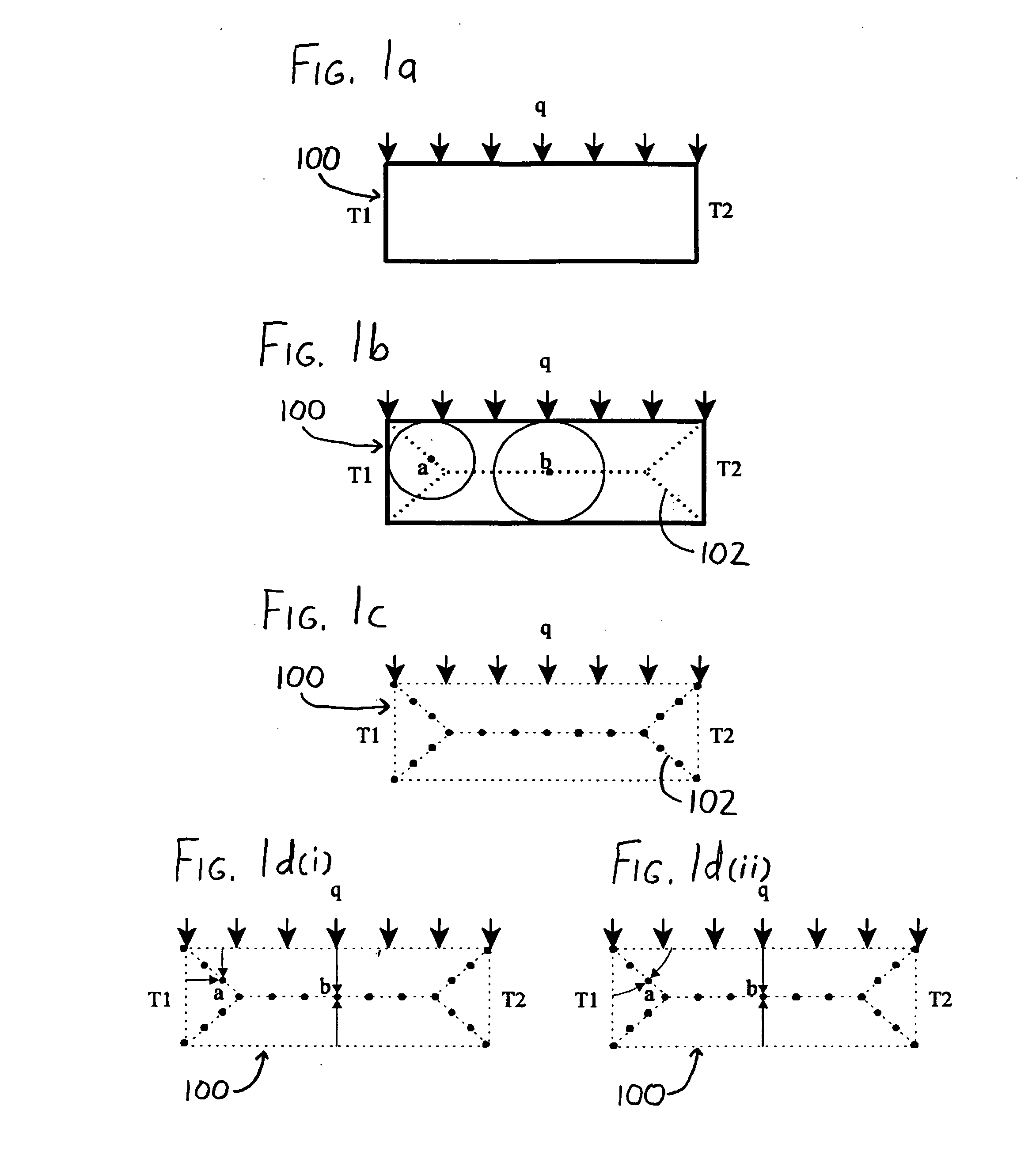
[0056] To illustrate the foregoing method, consider a simple engineering analysis problem:

∇2u=0 in Ω

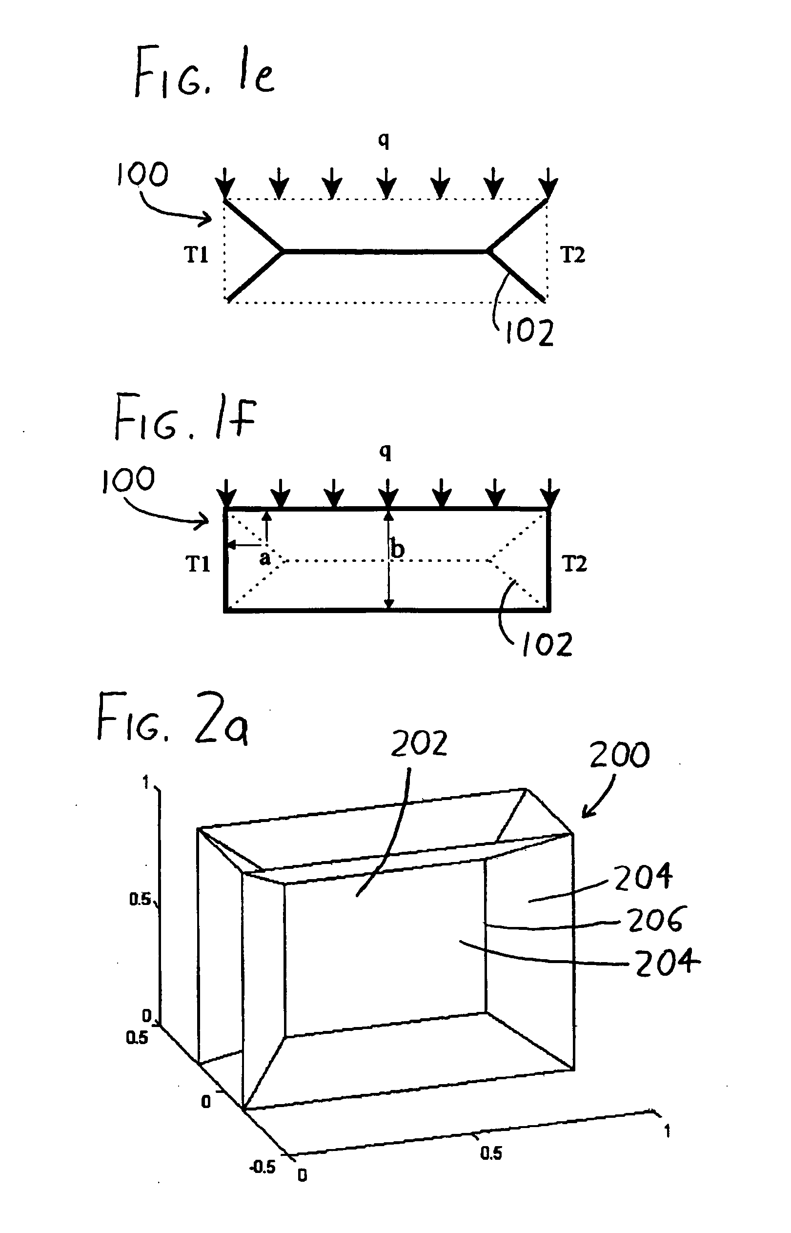
having boundary conditions u|Γ=û, where Ω is a cuboid (as in FIG. 2) of dimension (1, 1, 2H), H<0.5, and the exact solution is u=û=x+y+z.

[0057] Since the cuboid domain is a simple one, the skeleton (medial axis) can be computed to machine-precision accuracy. Since the exact solution is linear, and since the trial function (Equation (8)) is linear, the computed solution ucomputed should closely conform to u. TABLE 1 illustrates the results in the form of the maximum error e=max∥u−ucomputed∥ over the entire skeletal mesh for various values of H.

TABLE 1He = max∥u − ucomputed∥0.253.21e−150.13.02e−150.051.65e−15

Note that as H grows smaller—i.e., as the cuboid grows thinner—the error grows smaller.

example 2

[0058] Consider a slightly more complex problem:

∇2u=−1 in Ω

[0059] having boundary conditions u|Γ=0, where Ω is the “tuning fork” shown in FIG. 4a (and having a skeletal mesh computed as in FIG. 4b). Since exact solutions for the posed problem are not available, the computed solution can be compared to a full 3-D finite element mesh solution calculated by use of FEMLAB (Comsol Inc., Burlington, Mass.), a popular CAD / CAE commercial software package. TABLE 2 compares the maximum value of the computed field on the skeletal mesh against the FEMLAB solution for two different values of H, and also presents the approximate CPU time for the two methods. Note that the CPU time for the skeletal mesh includes the time needed to calculate the medial axis and generate the mesh thereon.

TABLE 2H3-D FEMSkeletal Mesh0.2max∥ucomputed∥1.41e−31.7e−3CPU Time (s)7.24.10.1max∥ucomputed∥3.1e−33.3e−3CPU Time (s)18.44.3

Note from TABLE 2 that the loss in accuracy arising from use of the skeletal mesh is sm...

example 3

[0060] In the foregoing experiments / examples, the numerical axes were computed to a high degree of accuracy. Thus, the question remains whether computed solutions would still be acceptable if the medial axes were approximated. As per the observations in Hammerlin, G., Hoffmann, K. H., Numerical Mathematics, New York, Springer-Verlag (1991), it is expected that data perturbations would have minimal effect on the computed solution owing to the underlying elliptic nature of the partial differential equations noted at the outset of this document (as well as others). This is confirmed in the following experiment.

[0061] Consider the L-shaped bracket of FIG. 5a, which is subject to the Laplacian problem u=û=x+y+z. Then consider if each point on the exactly-computed medial axis (and its mesh) was artificially perturbed by a maximum magnitude of ε (as an example, see FIG. 5b). TABLE 3 compares the computed solution for the perturbed mesh against the exact solution.

TABLE 3e = max∥u − ucomp...


PUM


Abstract

A method for simplifying engineering analysis of CAD geometric models, one which retains much of the accuracy of detailed finite element (FE) analysis while avoiding its computational burdens, is described. A skeleton, such as an exact or approximate medial mesh, is defined within the model, and the skeleton is then meshed. Known field values (physical values of interest, and/or their derivatives) are then “projected” onto the skeleton, as by interpolation or coordinate transformation, and these field values and the governing equations for the model and its engineering problem are then used to solve for unknown field values across all or desired portions of the skeletal mesh. The newly-determined field values may then be projected outwardly from the skeletal mesh to the remainder of the geometric model, again via interpolation or other methods. The method is found to be particularly efficient and accurate (again in comparison to standard FE methods) when applied to thin geometric objects, e.g., metal or plastic sheet, ribbed plates, thin cavities in plastics-forming molds, etc.

Description

STATEMENT REGARDING FEDERALLY SPONSORED RESEARCH [0001] This invention was made with United States government support awarded by the following agencies: [0002] National Science Foundation (NSF) Grant No(s). DMI-0322134 The United States has certain rights in this invention.FIELD OF THE INVENTION [0003] This document concerns an invention relating generally to methods for solution of boundary value problems in geometric models (e.g., CAD models and the like) via finite element and other analysis methods, and more specifically to boundary value problem analysis methods which are particularly applicable to thin objects (i.e., objects having at least one dimension which is small in relation to its other dimensions). BACKGROUND OF THE INVENTION [0004] In engineering fields, geometric modeling of objects and the engineering analysis of the behavior of the modeled objects are extremely important activities. Modeling is generally performed by constructing a representation of an object's geo...

Claims


Application Information

Patent Timeline
Patent Type & Authority Applications(United States)
IPC IPC(8): G06F17/10
CPCG06F17/5018G06F2217/42G06F2217/41G06F30/23G06F2113/22G06F2113/24
Inventor SURESH, KRISHNAN
Owner WISCONSIN ALUMNI RES FOUND
Why Eureka
Try Eureka