[0008] The
advantage of the present invention is essentially that a
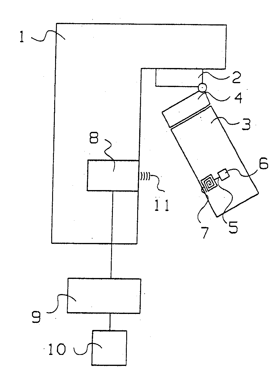
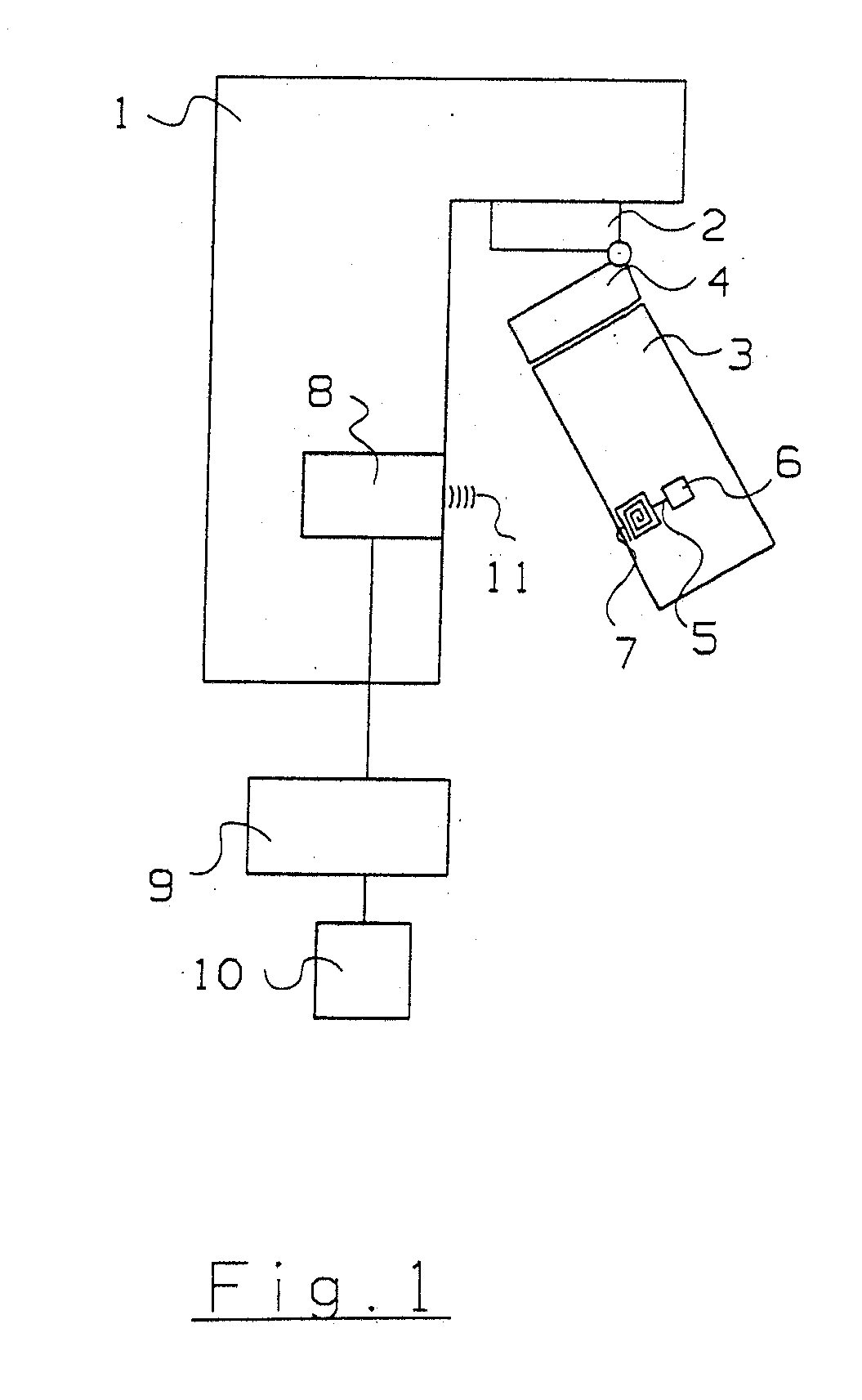
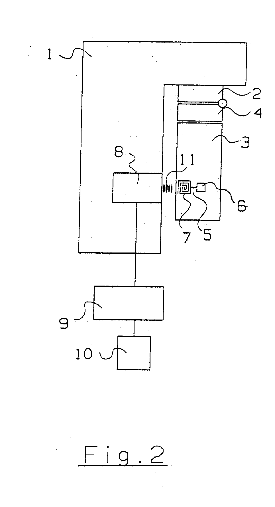
carbon dioxide absorber arranged on the respirator has a transponder with a
memory chip, on which a specification of the absorbent being used as well as the current state of consumption are stored. A transponder
polling device provided at the respirator reads data from the memory
chip, on the one hand, and calculates an updated state of consumption, which will again be stored in the memory
chip, from the operating data of the respirator. For example, phases of readiness, during which little or no absorption of carbon dioxide takes place, or the duration of mechanical
respiration can be detected as operating data. Since the updated state of consumption is stored again on the memory
chip, the depletion of the absorbent can also be determined when the
carbon dioxide absorber is connected to another respirator. The product life of the
carbon dioxide absorber can thus be reconstructed and carbon dioxide absorbers that were stored for an excessively long time and are no longer fully suitable for use can be recognized. Besides the current state of consumption, it is useful to store the type of the absorber, the type of the
breathing lime being used, the date of manufacture and the
expiration date on the memory chip.
[0009] It is advantageous to also store additionally a
manufacturer code on the memory chip. The
manufacturer code is likewise detected by the transponder
polling device and compared with a
list of permissible manufacturers in an evaluating unit of the respirator. A release
signal that makes possible the operation of the respirator is generated in case of agreement. It is thus achieved that only accessories of authorized suppliers can be connected to the respirator.
[0010] The data on the memory chip are advantageously evaluated only if the connection element of the carbon dioxide absorber has snapped completely into the rapid action
coupling of the respirator. The antenna and the transmission power of the transponder polling device are designed for this such that the content of the memory chip can be read only if the carbon dioxide absorber has snapped in. A mechanical coding may additionally also be present between the connection element and the rapid action coupling in order for the absorber to be able to be introduced in a preferred position only to reduce interface tolerances. The data of the memory chip may be evaluated only if the connection element has snapped completely into the said rapid action coupling.
[0011] Data on the operation of the carbon dioxide absorber are advantageously determined from the
breathing gas flow through the carbon dioxide absorber and the carbon dioxide concentration on the side on which the flow reaches the carbon dioxide absorber. The mode of
respiration may additionally also be included in the calculation of the operating data. The degree of depletion of the absorber can be determined in the evaluating unit from the operating data and the specification of the breathing
lime being used, such as type and lime volume and displayed on a display unit in the form of a percentage depletion of the absorber. A simplified display of the depletion of the absorber can be embodied with three light-emitting diodes. A
green light-emitting
diode indicates that the carbon dioxide absorber is ready to operate. A yellow light-emitting
diode signals, by contrast, the imminent depletion of the absorber, and a
red light-emitting
diode is activated when the carbon dioxide absorber is no longer ready for use.
[0012] An exemplary embodiment of the present invention is shown in the drawings and will be explained in greater detail below. The various features of novelty which characterize the invention are pointed out with particularity in the claims annexed to and forming a part of this disclosure. For a better understanding of the invention, its operating advantages and specific objects attained by its uses, reference is made to the accompanying drawings and descriptive matter in which preferred embodiments of the invention are illustrated.

