Illumination configuration for imaging-type optical encoders

Active Publication Date: 2006-12-21
MITUTOYO CORP
View PDF3 Cites 9 Cited by
  • Summary
  • Abstract
  • Description
  • Claims
  • Application Information

AI Technical Summary

Benefits of technology

[0012] In accordance with another aspect of the invention, to enhance or insure the uniformity of the illumination in the field of view, in various embodiments it may be advantageous that the dimension of the imaged field of view is less than the diameter of the clear aperture of the condenser lens, or more conservatively, substantially less.
[0013] In accordance with another aspect of the invention, in various embodiments a method for illuminating a telecentric system includes placing a diffuser in the path of the light emitted from a collimating or nearly-collimating lens. With proper selection of the diffuser characteristics, due to the collimated nature of the light exiting the lens and relatively small distance from the diffuser to the scale, this configuration may generate a uniform, diffuse illumination with the illumination concentrated in a beam diameter that is only slightly larger than the clear aperture of the

Problems solved by technology

If such “high intensity” portions exist (in a non-uniform image), then the measurement accuracy is disproportionately reduced if they are obscured or displaced.
In telecentric systems, uniform image illumination can be difficult to achieve under a variety of circumstances.
An additional problem may arise because a periodic scale is to be illuminated and i

Method used


Image

  • Illumination configuration for imaging-type optical encoders
  • Illumination configuration for imaging-type optical encoders
  • Illumination configuration for imaging-type optical encoders

Examples


first embodiment

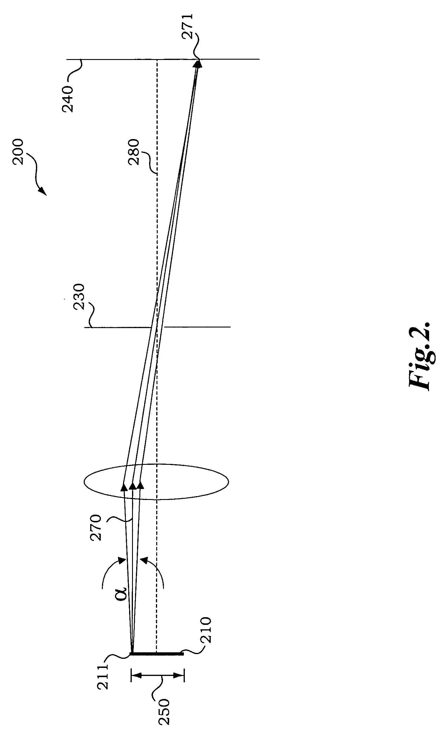
[0030]FIG. 3 is a diagram of an illumination configuration 300 for an imaging-type optical encoder in accordance with the present invention. The illumination configuration 300 includes a scale object 310 arranged at a distance L from a condenser lens 320, and an illumination source 390 with an emitter area that has a nominal dimension w, arranged at a focal distanced from the lens 320. A FOV dimension 350 on the scale object 310 is defined by the characteristics of an optical system (not shown) that images the scale object 310. For example, the FOV may be defined by the magnification of the imaging optics and the size of the field stop (e.g., the detector dimensions). The FOV may also be limited based on the optical performance of the imaging lens. In this case a mechanical or software field stop may be provided to limit the FOV to a dimension smaller than the detector dimensions. Various considerations related to the FOV of a miniature imaging-type encoder are discussed further bel...

second embodiment

[0042]FIG. 7 is a diagram of an illumination configuration 700 for an imaging-type optical encoder in accordance with the present invention. The illumination configuration 700 is similar to the illumination configuration 300, and includes a scale object 710 arranged at a distance L from a condenser lens 720, which may be a collimating lens, and an illumination source 790 with an emitter area that has a nominal dimension w. A FOV dimension 750 on the scale object 710 is defined by the characteristics of an optical system (not shown) that images the scale object 710. In addition, the illumination configuration 700 includes a diffuser 715 located between the condenser lens 720 and the scale object 710. The diffuser 715 may be utilized to help reduce changes in the irradiance distribution due to changes in the pitch or roll alignment of the illumination system optical elements relative to the scale object 710. Such misalignments may displace an illumination distribution across the FOV, ...


PUM


Abstract

An illumination configuration for imaging-type optical encoders is provided. The illumination configuration generates uniform brightness images of scales and two-dimensional structures when utilizing telecentric imaging optics in the encoder readhead. In one embodiment, a desirable uniform irradiance distribution is created across the field of view by illuminating with a collimated or quasi-collimated beam, but insuring that the illumination is sufficiently incoherent that potential self-images arising from periodic structures on the scale are suppressed. In one embodiment, the ratio of an effective emitter size to a focal length of the collimating lens falls within a selected range, so as to assure relatively uniform illumination across the field of view and still provide sufficiently incoherent illumination. In another embodiment, a diffuser is placed over the collimating lens, which assists in producing uniform illumination even when the direction of illumination varies relative to the scale due to misalignment between the readhead and the scale surface.

Description

FIELD OF THE INVENTION [0001] The present invention relates to imaging-type optical encoders, and more particularly, to an illumination configuration that generates desirable measurement images of one-dimensional and two-dimensional scales, including periodic scales. BACKGROUND OF THE INVENTION [0002] Various optical encoders are known that use a readhead having a relatively simple optical arrangement that includes a lens to provide an image of a scale pattern to a photodetector arrangement in the readhead. This type of system, which uses incoherent light to image a scale pattern onto an optical detector to thereby measure the relative or absolute displacement of the scale pattern, is called an imaging-type encoder. One such system is disclosed in U.S. Pat. No. 5,539,519, to Takagi et al., which is incorporated herein by reference. The system described in the '519 patent includes an encoder plate having a periodic slit pattern. A light source illuminates the slit pattern to form a p...

Claims


Application Information

Patent Timeline
IPC IPC(8): G01D5/34
CPCG01D5/34715
Inventor ALTENDORF, ERIC H.
Owner MITUTOYO CORP
Why Eureka
Try Eureka