
Energy efficient pressure less steam generator

a technology of electrical operation and steam generator, which is applied in the direction of air humidification system, lighting and heating apparatus, heating types, etc., can solve the problems of low system efficiency, difficult portability, and bulky steam generators, and achieve high energy efficiency, easy steam generation, and low cost

Active Publication Date: 2017-05-30
VEMPATI VENKATA SUNDERESWAR RAO
View PDF35 Cites 0 Cited by
  • Summary
  • Abstract
  • Description
  • Claims
  • Application Information

AI Technical Summary

Benefits of technology

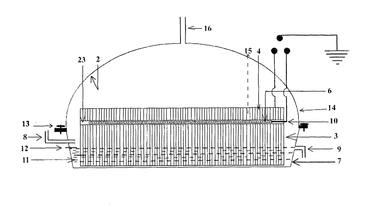
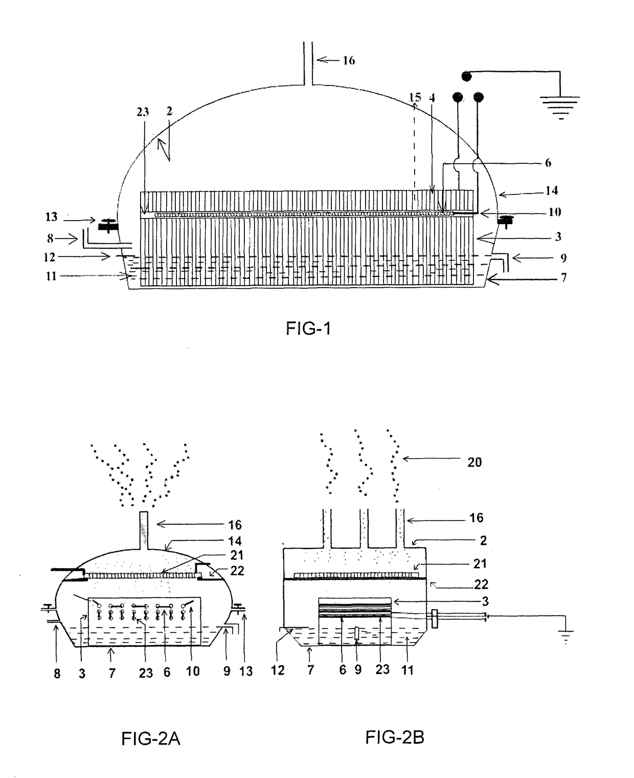
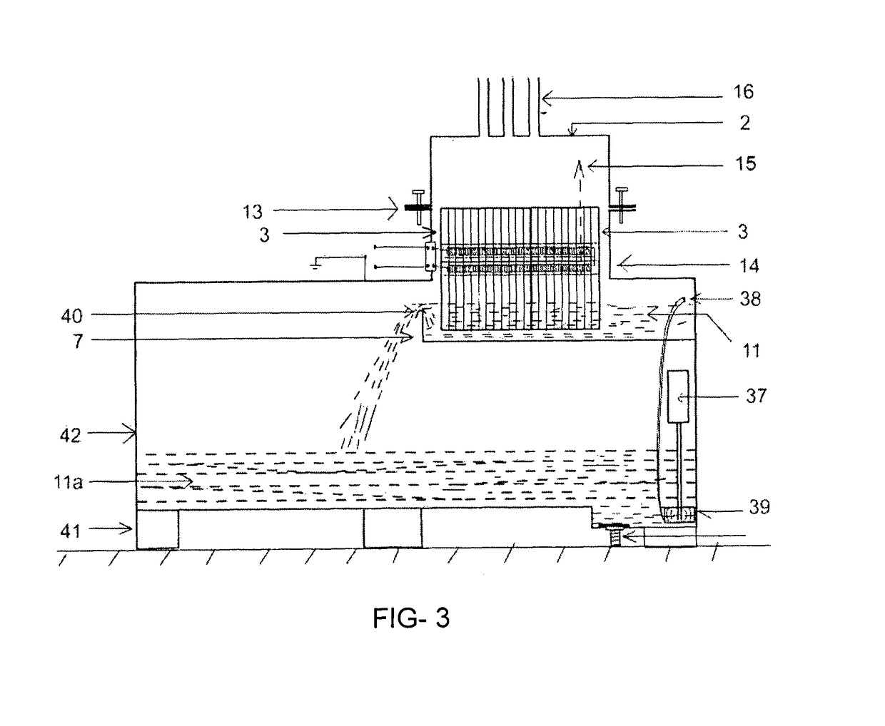
[0049]Accordingly when water is pumped into the tray of the steam generator through the water inlet pipe, water level rises up to the maximum water level position after which the excess water will drain out from the drain pipe or overflows at the lip and maintains the water level at a constant position. When the water comes into contact with the porous ceramic honeycomb body, the porous ceramic body will immediately start absorbing water and due to the fine interlocked pores in the body and the body acts like a multiple capillary network arrangement, sucking up water to all the dry portions of the ceramic honeycomb, water absorption will be preferentially high along the vertical direction while water movement will be slow in the horizontal direction due to the existence of wall junctions. Since the ceramic honeycomb provides a very high surface area because of its various walls and channels, along with the inherent porosity of the low density ceramic material, a relatively high surface area and consequently a high spread of absorbed water is created.
[0051]According to another preferred embodiment under the invention a secondary heating unit mounted in a frame and resting on supports brackets at a distance of at least one inch or higher above the ceramic honeycomb in such a fashion that the steam emerging out of the vertically oriented channels of the ceramic honeycomb will passes through the secondary heater which increases the steam temperature considerably. Water is continuously fed to the tray through the inlet port and the excess water drain pipe helps in maintaining constant water level and the steam outlet nozzles in the roof of the main body of the steam generator allows steam to be conveyed to the usage area. The Roof comprises of one or more Nozzles as means to allow generated steam to pass through for further use. Another preferred embodiment offers a single piece of porous low density ceramic body in a housing made of SS 316 L material having a means to store small and limited quantities of water and means for inlet and outlet of water, while the porous ceramic body is provided with means in the form of holes, to install electrical resistance heating element in the holes in such a fashion that the bottom most part of the heating element is always above the maximum water level in the tray of the housing, and the housing having means in the form of nozzles for discharge of the steam generated for further use.
[0053]It is observed that by this invention we can generate super heated steam without any application of pressure or pressure vessels and without any heat loss to the steam during its travel to the superheating stage that too without any moving parts or accessories in the steam generator. This makes it a most convenient device, as it can be scaled up or extrapolated for higher volumes of steam, higher temperatures of steam, miniaturized models, fit to scale at any place, and offers the best solution for making the steam generation an easy task.
[0054]The improved electrical low pressure super heated steam generator as disclosed in this invention provides minimum assembled components; the evaporation rate is very high without any bubbling or rigorous reaction and is highly energy efficient. The inventions is not only efficient but also offers various opportunities by varying temperatures, production of dry steam or wet steam etc by simple manipulation of the heater temperature and / water in the tray

Problems solved by technology

Most of these steam generators are bulky, complicated, and are not easily portable due to the water reservoir, boilers and pressure vessels involved etc while the efficiency of the systems is also low as most of the stored water has to be continuously boiled or heated and kept hot throughout the evaporation process.
The surface area that can be heated is limited and the evaporation efficiency is less.
Steam generators with submerged electric resistors have draw backs of higher start up times running to about 10 minutes and have an added problem of overheating in absence of water and scaling.
Dragging of water drops is an occasional problem due to existence of boiling.
Though this device claims many improvements, it still has many limitations like submerged heating element.
Limited contact area, complicated manufacturing procedure.
Though this device claims efficiency, the bulk of the water is heated and thereby reducing its efficiency.
It can be seen that the device still has to depend on heating the bulk of water first and then evaporate to and superheat resulting in poor efficiency.
The instantaneous steam generation has a short regeneration period which allows re-steaming of an oven during a baking cycle however it is a very complicated unit and lacking in ease of manufacture.
Also efficiency of evaporation is low.
Though inefficient in energy utilization, the device may operate for large scale operations.
But on a small scale, the manufacture may be more cumbersome.
Summing up, the prior art disclosures suffer from the following often observed limitations1) Construction requires high pressure pumps, pressure vessels, seamless pipe lines and insulated body in addition to being, expensive to construct.2) The heating electrode is submerged in water resulting in scaling on heater and severe bubbling resulting in droplets of water in steam and also early heater failure3) Very limited contact surface area for efficient evaporation to take place4) Water stored for evaporation is heated continuously.5) Poor energy utilization6) Rigorous safety standards to be followed.

Method used


Image

  • Energy efficient pressure less steam generator
  • Energy efficient pressure less steam generator
  • Energy efficient pressure less steam generator

Examples


Embodiment Construction

[0065]Other features and advantages of the present invention should become apparent from the following description of the preferred process and read in conjunction with the accompanying drawings, which illustrate, by way of example, the principles of the invention.

[0066]Referring to the most preferred embodiment shown in FIG. 1, the energy efficient electrically operated steam generating device (1) is having a main body (14) made from SS316 L or equivalent material, housing a porous ceramic honeycomb (3) with plurality of parallel channels (4) all vertically oriented and having electrical resistance heating element (6) installed inside the drilled holes (23) in the ceramic honeycomb (3) in such a way that the heating element(6) and the holes (23) are both mutually parallel and both are perpendicularly positioned to the axis (15) of the honeycomb channel (4). The ceramic honeycomb (3) is positioned inside the water (11) in the tray (7) and the maximum water level (12) is always maint...


PUM


Abstract

An energy efficient electrically operated steam generator is capable of producing pressure less high temperature as well as superheated steam. It comprise of main body (14) defined by side wall, roof (2) and open bottom, securely fixed to the rim of water holding tray (7). Said roof is provided with steam outlet nozzles (16) to allow the steam to emerge out of the steam generator. A porous ceramic honeycomb (3) with plurality of parallel channels (4), and grooves (5) or holes (23) are created therein for inserting heating element (6). One end of all the channels (4) is always submerged in water (11) in tray (7), and the other end of most of the channels is open to the roof and both ends of the heating element are connected to the power source for heating the water to generate steam.

Description

FIELD OF INVENTION[0001]This invention relates to an energy efficient electrically operated pressure less steam generator having a housing, with one or more heating electrodes introduced into low body density Ceramic honeycombs with their channels vertically oriented and parallel to one another with one end of all the channels resting in a tray of water with limited water level wherein water never exceeding this level such that these electrical resistance heating electrodes that are always at least 10 millimeters above the water level. More especially it is capable of producing pressure less superheated steam by introducing secondary electrical heater at a height of more than one inch over the ceramic honeycomb in such a fashion that most of the steam passes through the said secondary heater coil arrangement and thus increase the steam temperature.BACKGROUND OF THE INVENTION[0002]Many methods have been devised to generate steam and many are working even today. Most of these steam ge...

Claims


Application Information

Patent Timeline
Patent Type & Authority Patents(United States)
IPC IPC(8): F24F6/00F24F6/08F22B1/28
CPCF22B1/285F22B1/284Y02P80/15
Inventor VEMPATI, VENKATA SUNDERESWAR RAO
Owner VEMPATI VENKATA SUNDERESWAR RAO
Learn More