
Vibration motor

a technology of vibration motor and conduction terminal, which is applied in the direction of dynamo-electric machines, electrical equipment, supports/enclosements/casings, etc., can solve the problems of easy lateral shaking of springy conduction terminals, electrical connection disturbance, and extremely springy conduction terminals, so as to reduce unnecessary vibration, increase work efficiency, and easily break off

Inactive Publication Date: 2006-12-21
SANYO SEIMITSU
View PDF16 Cites 16 Cited by
  • Summary
  • Abstract
  • Description
  • Claims
  • Application Information

AI Technical Summary

Benefits of technology

[0008] Therefore, an object of the present invention is to provide a vibration motor able to greatly suppress lateral shaking of conduction terminals.
[0010] The spacer is formed integrally with the end cap and abuts against the circumferential surface of the motor. Further the power contacts on the board side are elastically retractable. Therefore, it is not necessary to give the spacer on the vibration motor side and the plate-shaped conduction terminals any special elasticity and possible to suppress unnecessary vibration. Further, the first contact face integrally has a first abutting part abutting against a first side face of the spacer and the second contact face integrally has a second abutting part abutting against a second side face different from the first side face of the spacer, so the distance between the contact faces can be constrained and their lateral shaking can be greatly suppressed.
[0012] Since the abutting parts press against the spacer at positions furthest away from the base ends of the plate-shaped conduction terminals, they provide support at the two ends in structure and can suppress unnecessary vibration. Further since the abutting parts are formed near the outer edges of the contact faces, it is possible to increase the widths of the contact faces to secure greater room for contact with the power contacts on the board side, and the pair of contact faces do not have to project out from the motor case.
[0014] The attachment piece of the terminal part is held and the pair of the bent parts are attached and connected to the pair of motor power parts and, in that state, the pair of plate-shaped conduction terminals are held at a predetermined distance by being connected by the attachment piece in a forked manner, so the plate-shaped conduction terminals can be connected while maintaining parallelism without separating. Further, since the attachment piece stretches out in the radial direction over the end face of the end cap body, it is possible to hold the attachment piece and bend it at the separating groove to easily break it off so as to remove the attachment piece from the plate-shaped conduction terminals. This increases the work efficiency when attaching the plate-shaped conduction terminals.
[0015] In the present invention, the spacer is formed integrally with the end cap and abuts against the circumferential surface of the motor. Further the power contacts on the board side are elastically retractable. Therefore, it is not necessary to give the spacer on the vibration motor side and the plate-shaped conduction terminals any special elasticity and possible to suppress unnecessary vibration. Further, the first contact face integrally has a first abutting part abutting against a first side face of the spacer and the second contact face integrally has a second abutting part abutting against a second side face different from the first side face of the spacer, so the distance between the contact faces can be constrained and their lateral shaking can be greatly suppressed.

Problems solved by technology

However, the vibration of the vibration motor itself and external vibration or impact force results in the springy conduction terminals easily laterally shaking on the power patterns and electrical connection being disturbed.
However, the conduction terminals are extremely springy.
Therefore, it has unnecessary vibration separate from the rotational vibration of the eccentric weight.
The conduction terminals are even more susceptible to lateral shaking.

Method used


Image

  • Vibration motor
  • Vibration motor
  • Vibration motor

Examples


Embodiment Construction

[0023] Next, an embodiment of the present invention will be explained based on the attached drawings.

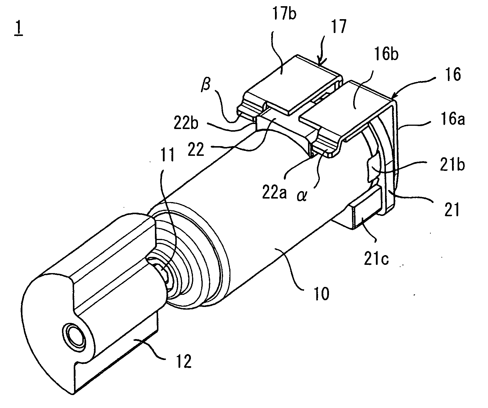
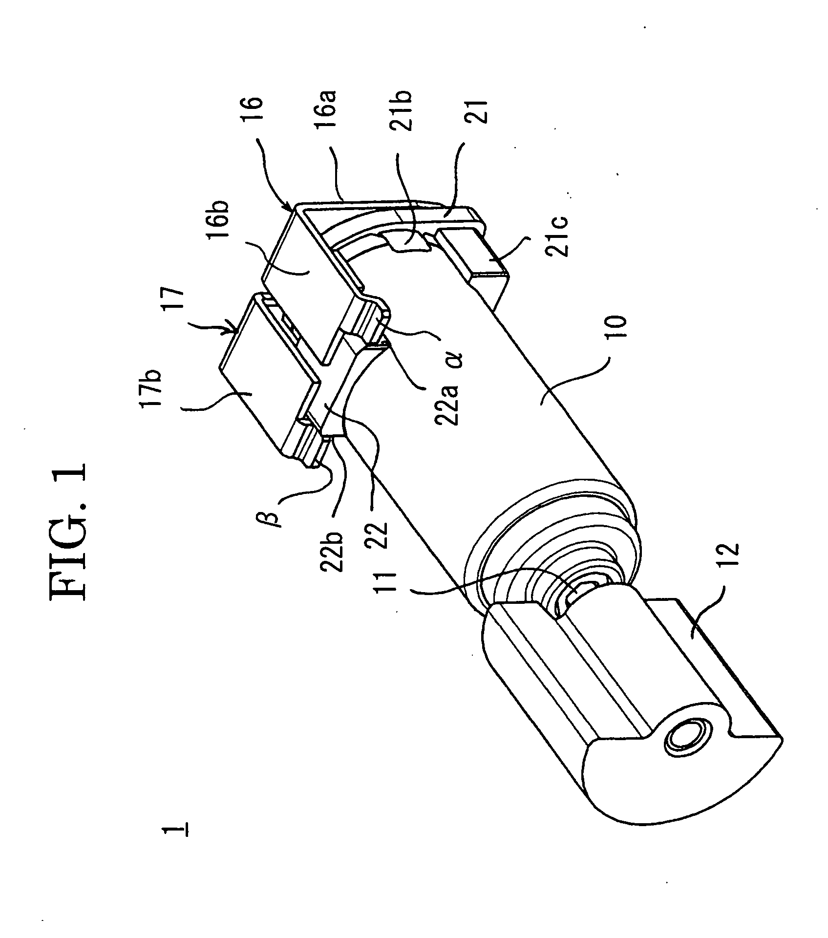
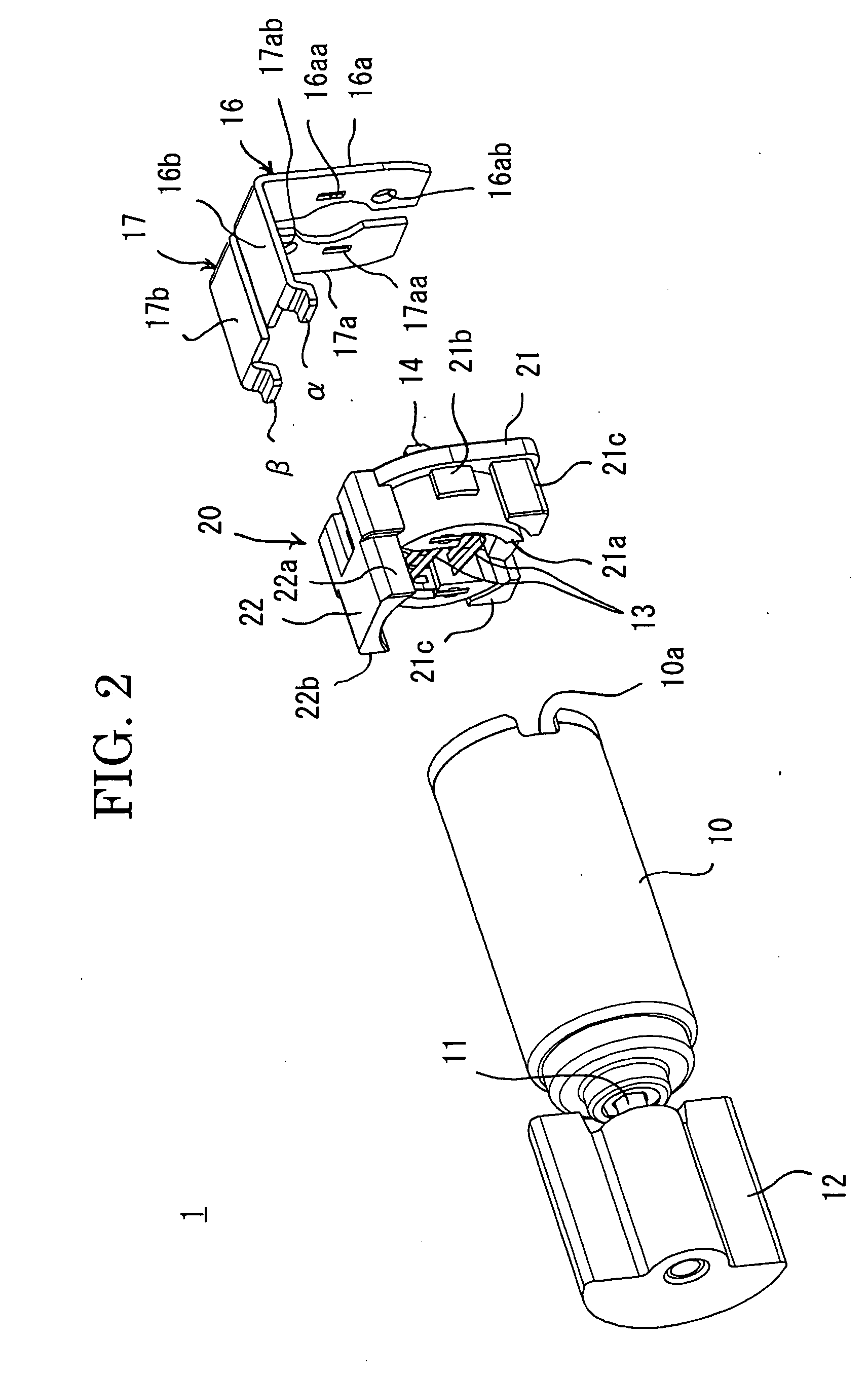
[0024]FIG. 1 is an assembled perspective view of a vibration motor according to an embodiment of the present invention, FIG. 2 is a disassembled perspective view with part of the vibration motor detached; FIG. 3 is a disassembled perspective view of the state shown in FIG. 2 seen from another angle; FIG. 4 is a perspective view showing a pair of plate-shaped conduction terminals used for the vibration motor; and FIG. 5 is a side view of the state of mounting the vibration motor on a board.

[0025] The vibration motor 1 of this example is comprised of a cylindrically shaped motor case 10 from which projects a motor shaft 11 to which an eccentric weight 12 is attached. The motor case 10 is provided inside it with a magnet (not shown) fixed to its inner circumference, a rotor (not shown) fixed to the motor shaft 11, and a commutator (not shown) fixed to the motor shaft 11 and electrical...


PUM


Abstract

A vibration motor able to greatly suppress lateral shaking of conduction terminals, provided with a pair of motor power parts provided at an end cap closing an open end of a motor case, a pair of plate-shaped conduction terminals including contact faces for abutting against elastically retractable power contacts provided at the board side and connected corresponding to the motor power parts, and a spacer formed integrally with the end cap and abutting against a circumferential surface of the motor case to separate the contact faces from the circumferential surface, wherein the first contact face integrally has a first abutting part abutting against a first side face of the spacer and the second contact face integrally has a second abutting part abutting against a second side face different from the first side face of the spacer.

Description

CROSS-REFERENCE TO RELATED APPLICATIONS [0001] This application is based upon and claims a priority of Japanese Patent Application No. 2005-166686, filed Jun. 7, 2005, the contents being incorporated herein by reference. BACKGROUND OF THE INVENTION [0002] 1. Field of the Invention [0003] The present invention relates to a vibration motor having an eccentric weight, more particularly relates to a vibration motor mounted by making plate-shaped conduction terminals abut against elastically retractable power contacts provided on the board side. [0004] 2. Description of the Related Art [0005] In the past, in general, a vibration motor has a pair of springy conduction terminals and is mounted in a state with the conduction terminals made to abut against power patterns on the board side. However, the vibration of the vibration motor itself and external vibration or impact force results in the springy conduction terminals easily laterally shaking on the power patterns and electrical connect...

Claims


Application Information

Patent Timeline
Patent Type & Authority Applications(United States)
IPC IPC(8): H02K7/06
CPCH02K5/00H02K2211/03H02K7/061H02K5/225
Inventor TAKAGI, TAKAHIRONAKAMURA, MASATO
Owner SANYO SEIMITSU
Learn More