Actuator for operating a roller blind and method of operating such an actuator

a technology of roller blinds and actuators, applied in the direction of single-phase induction motor starters, ac motor direction control, electrical equipment, etc., can solve the problems of less accurate method and high cost of capacitors

Inactive Publication Date: 2006-12-21
SOMFY SAS
View PDF9 Cites 5 Cited by
  • Summary
  • Abstract
  • Description
  • Claims
  • Application Information

AI Technical Summary

Benefits of technology

[0009] The purpose of the invention is to provide an actuator and a method of operating an actuator that overcome the abovementioned problems and improve the actuators and methods known from the prior art. In particular, the actuator and the...

Problems solved by technology

Such capacitors are expensive.
However, as described below, such a method is less accurate than a measurement of the voltage at the t...

Method used


Image

  • Actuator for operating a roller blind and method of operating such an actuator
  • Actuator for operating a roller blind and method of operating such an actuator
  • Actuator for operating a roller blind and method of operating such an actuator

Examples


first embodiment

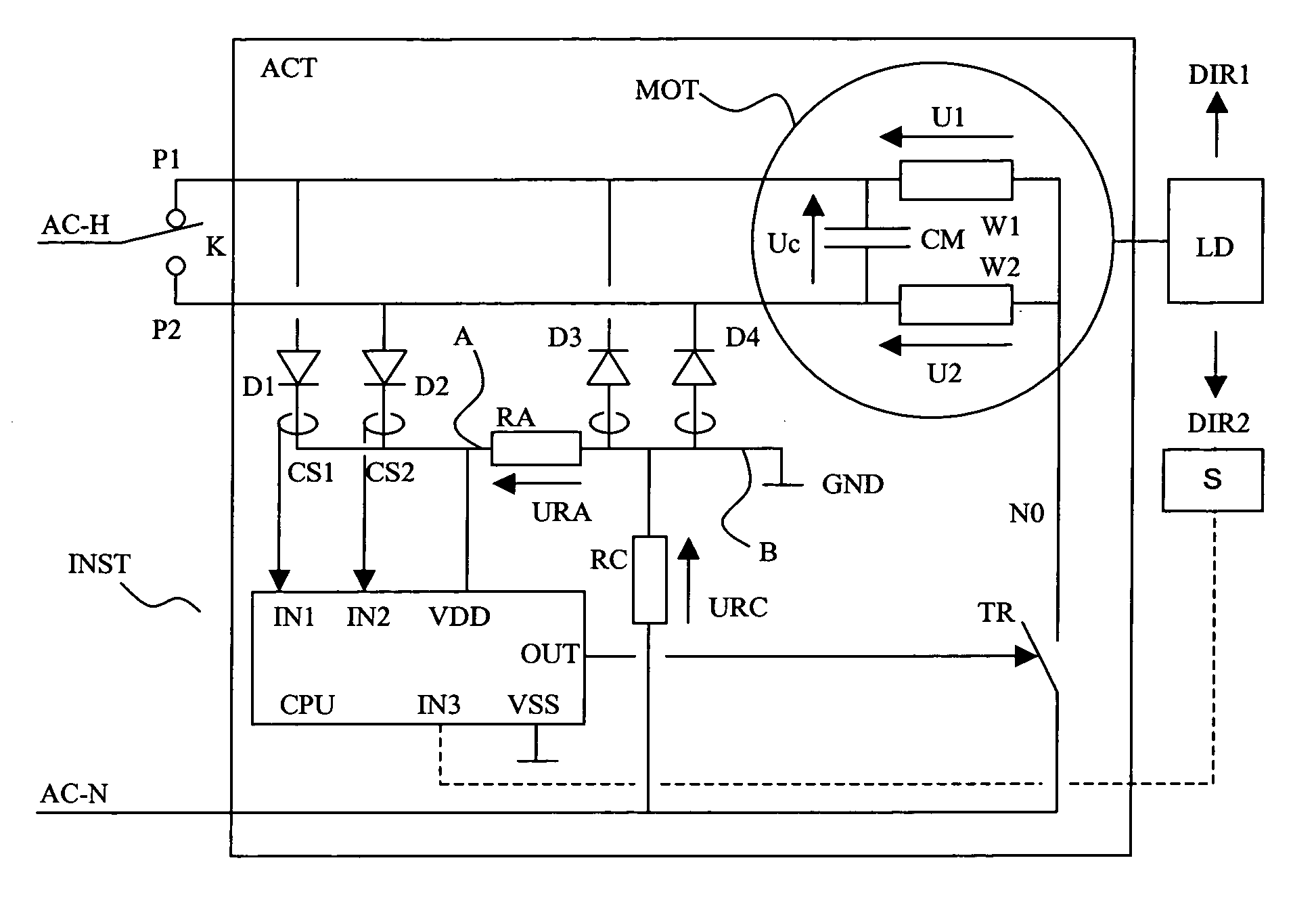
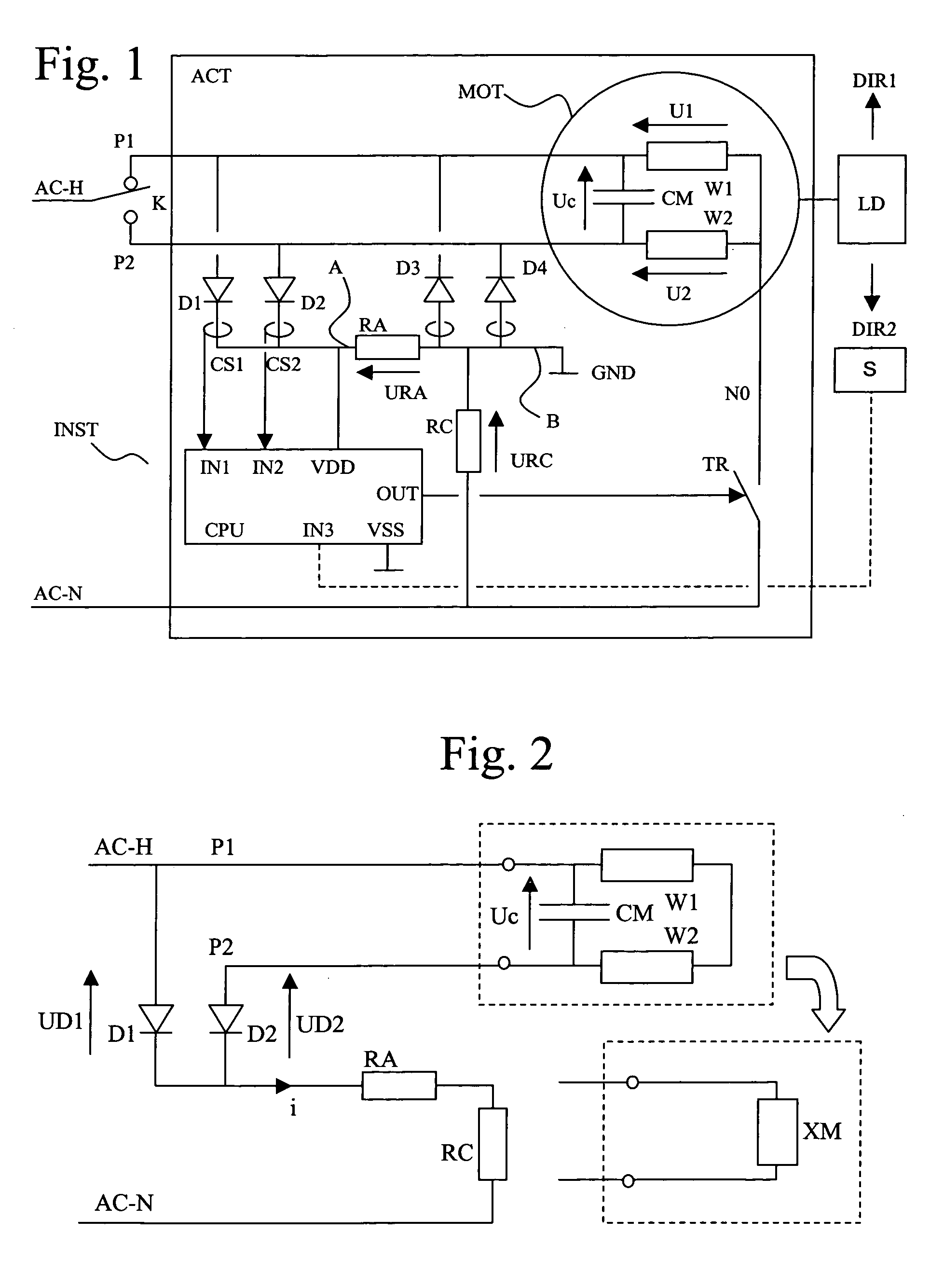
[0041]FIG. 2 is a simplified electrical circuit diagram of the actuator device when the controlled switch TR is open. The two windings W1 and W2 of the motor are then in series with each other and are in parallel with the motor capacitor C. All of the equivalent dipole XM is therefore either resistive and inductive, or resistive and capacitive.

[0042] When the phase conductor of the mains is connected to the first phase terminal P1 and when the mains voltage is positive, the current branch including the diode D1 short circuits the current branch including the equivalent dipole XM and the diode D2. In practice, if it is assumed that the diode D2 starts to conduct, the voltage UC at the terminals of the equivalent dipole is necessarily positive, therefore the voltage UD1 at the terminals of the diode D1 is greater than the voltage UD2. Since the voltage UD1 is limited (typically 0.8 V), the result is that the more the diode D2 conducts, the more the voltage at its terminals should decr...

second embodiment

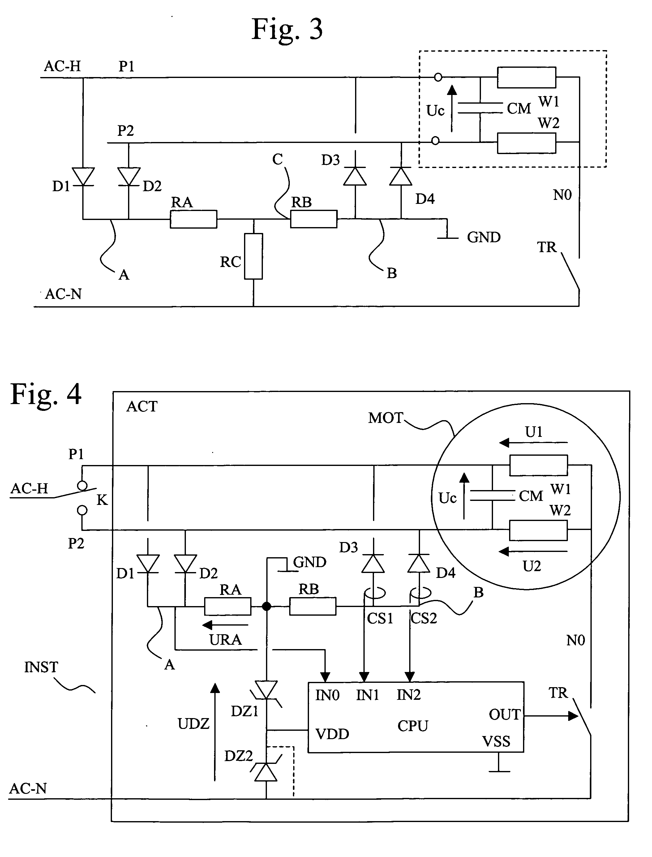
[0043]FIG. 3 represents in simplified form the actuator device in which the resistive circuit presents a T architecture between the points A and B and the neutral conductor. A resistor RB is now disposed between the point common to the resistors RA and RC of FIG. 1 and the point B identifying the common cathode of the diodes D3 and D4.

[0044]FIG. 4 represents a third embodiment of the actuator device in which the resistive circuit is also formed by a T between the points A and B and the neutral conductor. A resistor RB is disposed as previously. However, the resistor RC is replaced by two zener diodes DZ1 and DZ2 in opposition. In a variant of this third embodiment which constitutes the preferred embodiment of the invention, just one zener diode is used.

[0045]FIG. 5 represents an oscillogram over time of the voltages at the terminals of the windings of the motor and at the terminals of the motor capacitor CM in the case of a variant of the first embodiment represented in FIG. 1 in w...

third embodiment

[0073] A device according to a second variant of the device differs from the device described previously in that the zener diode DZ2 is replaced by a short circuit (dotted line in FIG. 4). This time, the voltage UDZ is zero when the zener diode DZ1 conducts forward and −UZ when it conducts in reverse. This imbalance tends to shorten the conduction times of the diodes D3 and D4. The main interest of this variant is that the start and end of conduction instants of the diodes D3 and D4 are now linked to the instants at which the voltages U2 or U1 are cancelled out. In particular, the voltage U1 is maximum (amplitude of the mains voltage) a quarter period after the end of conduction of the diode D3. In the conduction range of the diode D1, URA=U1.

[0074] In other words, it is possible with the assembly of FIG. 4 without the diode DZ2: [0075] to identify the control command applied by means of the control switch by analyzing the instantaneous switchings between the diodes D4 and D3, [0076...


PUM


Abstract

The actuator (ACT) is intended to be linked to phase (AC-H) and neutral (AC-N) conductors. It comprises a motor (MOT) provided with windings (W1, W1), a capacitor (CM) disposed between two ends of the windings and the terminals of which form a first (P1) and a second (P2) phase terminal. It includes a switch (TR) controlled by an electronic unit (CPU) to link the common end of the windings to the neutral conductor, at least one pair of diodes (D1, D2; D3, D4), the diodes of one and the same pair being connected by an electrode of the same type to a resistive circuit (RA, RB, RC, DZ1, DZ2) connected to the neutral conductor, the other electrode of each diode being respectively linked to the first and second phase terminals and means (CS1, CS2) of detecting the state of conduction of the diodes.

Description

[0001] The invention relates to an actuator defined by the preamble to claim 8. It also relates to a method of operating such an actuator. [0002] The actuator is intended to drive a moving load in a building, such as a closure or solar protection device, a projection screen or similar. BACKGROUND OF THE INVENTION [0003] A single-phase induction motor comprises a first winding and a second winding, these two windings presenting a common point linking one end of each winding. The other end of the first winding is linked to the first phase terminal and the other end of the second winding is linked to the second phase terminal. A motor capacitor CM is disposed between these two other ends. Thus, depending on whether a voltage is applied between the first phase terminal and the common point or between the second phase terminal and the common point, either the capacitor is placed in series with the second winding and the motor rotates in a first direction, or the capacitor is placed in se...

Claims


Application Information

Patent Timeline
IPC IPC(8): H02P3/18
CPCH02P23/0072H02P23/24
Inventor BRUNO, SERGE
Owner SOMFY SAS
Why Eureka
Try Eureka