Device for connecting a coaxial line to a coplanar line

a coaxial line and coplanar line technology, applied in the direction of multiple-port network, waveguide-type devices, coupling device connections, etc., can solve the problems of interference with the transmission and reflection properties at the point of connection, unsatisfactory effect, and inability to achieve the desired effect, etc., to achieve good resonance characteristics, short circuit, and increase the distance from the point of connection

Inactive Publication Date: 2006-12-21
SIEMENS AG
View PDF6 Cites 17 Cited by
  • Summary
  • Abstract
  • Description
  • Claims
  • Application Information

AI Technical Summary

Benefits of technology

[0011] The essential feature of the device according to the invention is to be considered as being that the metallization layer has a recess beginning at the point of connection between the coaxial plug and the coplanar line and running approximately symmetrical to the coplanar inner conductor and tapering in the direction of the coplanar inner conductor as the distance from the point of connection increases. Advantageously, the capacitive line load is compensated by a recess in the metallization of the rear face of the coplanar line in the vicinity of the point of transition to the coaxial line. To avoid resonances, in the design according to the invention, the edges of the recess run approximately symmetrical to the coplanar inner conductor and the recess tapers in the direction of the coplanar inner conductor as the distance from the point of connection increases, that is, edges of the recess that run parallel to each other are thus avoided. Particularly good resonance characteristics are achieved, for example, by using a triangular-shaped recess.
[0012] In a further advantageous embodiment of the device according to the invention, when a metallic substrate carrier layer is used, an indentation that is congruent with the recess or larger is provided in the substrate carrier layer. Thus a short circuit in the recess is advantageously avoided.

Problems solved by technology

This widening can lead to an undesirable increase in the capacitive wire load and therefore to an undesirable local reflection, which, at frequencies greater than 40 GHz, results in interference with the transmission and reflection properties at the point of connection.
Compensation by means of circuitry arrangements at a different point along the transmission path, as is usual in narrow band applications, does not produce the desired effect.
These indentations accommodate the substrate material used for the coplanar line, yet require relatively intensive machining work and are not therefore applicable when using commercially obtainable coaxial connectors (such as the Anritsu V115FCPW).
Here, too, relatively intensive machining work is required and the arrangement can only be configured with difficulty when commercially obtainable coaxial connectors are being used.

Method used


Image

  • Device for connecting a coaxial line to a coplanar line
  • Device for connecting a coaxial line to a coplanar line
  • Device for connecting a coaxial line to a coplanar line

Examples


Embodiment Construction

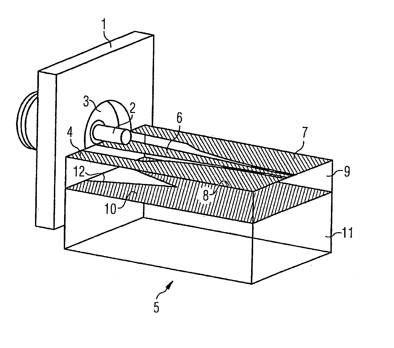
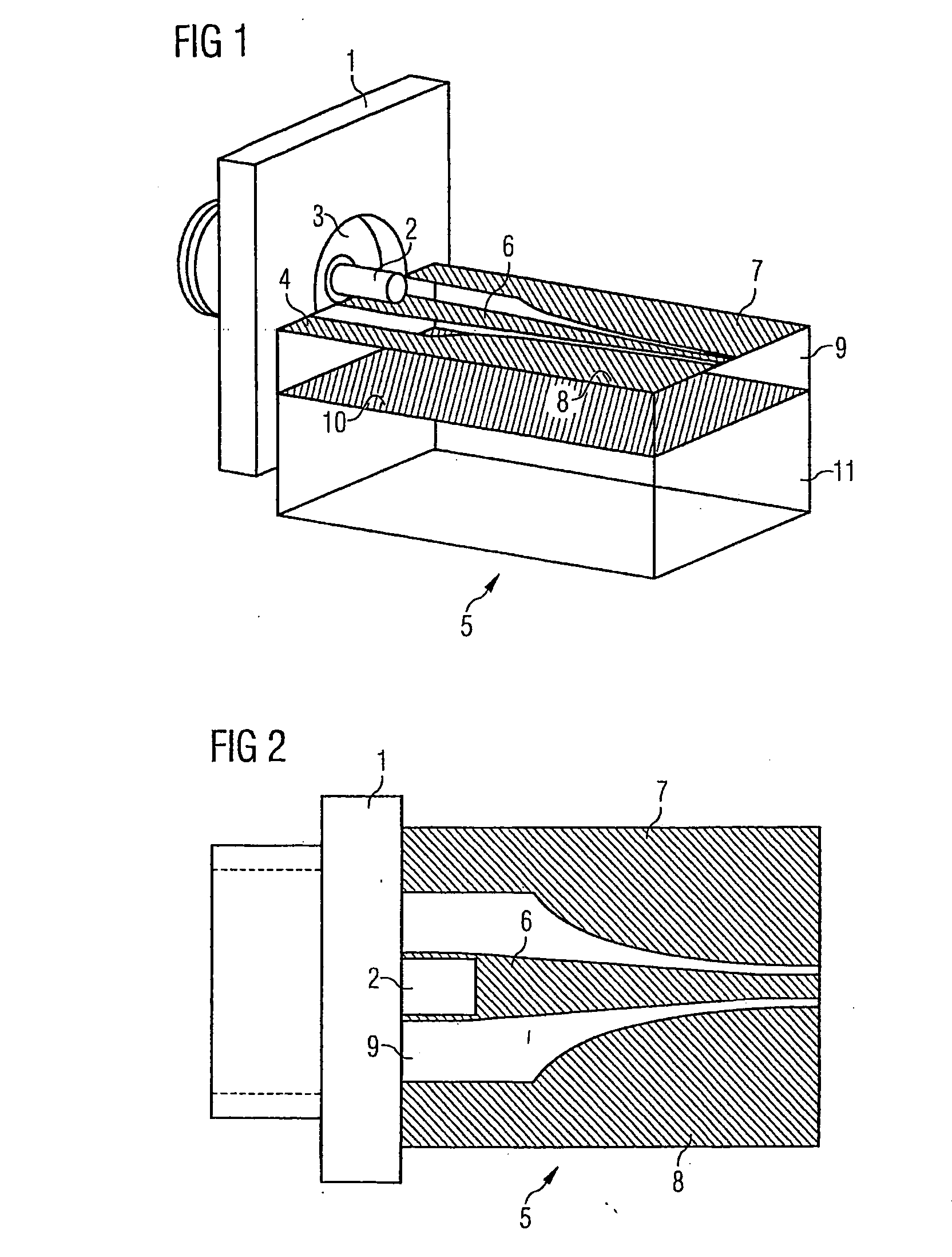
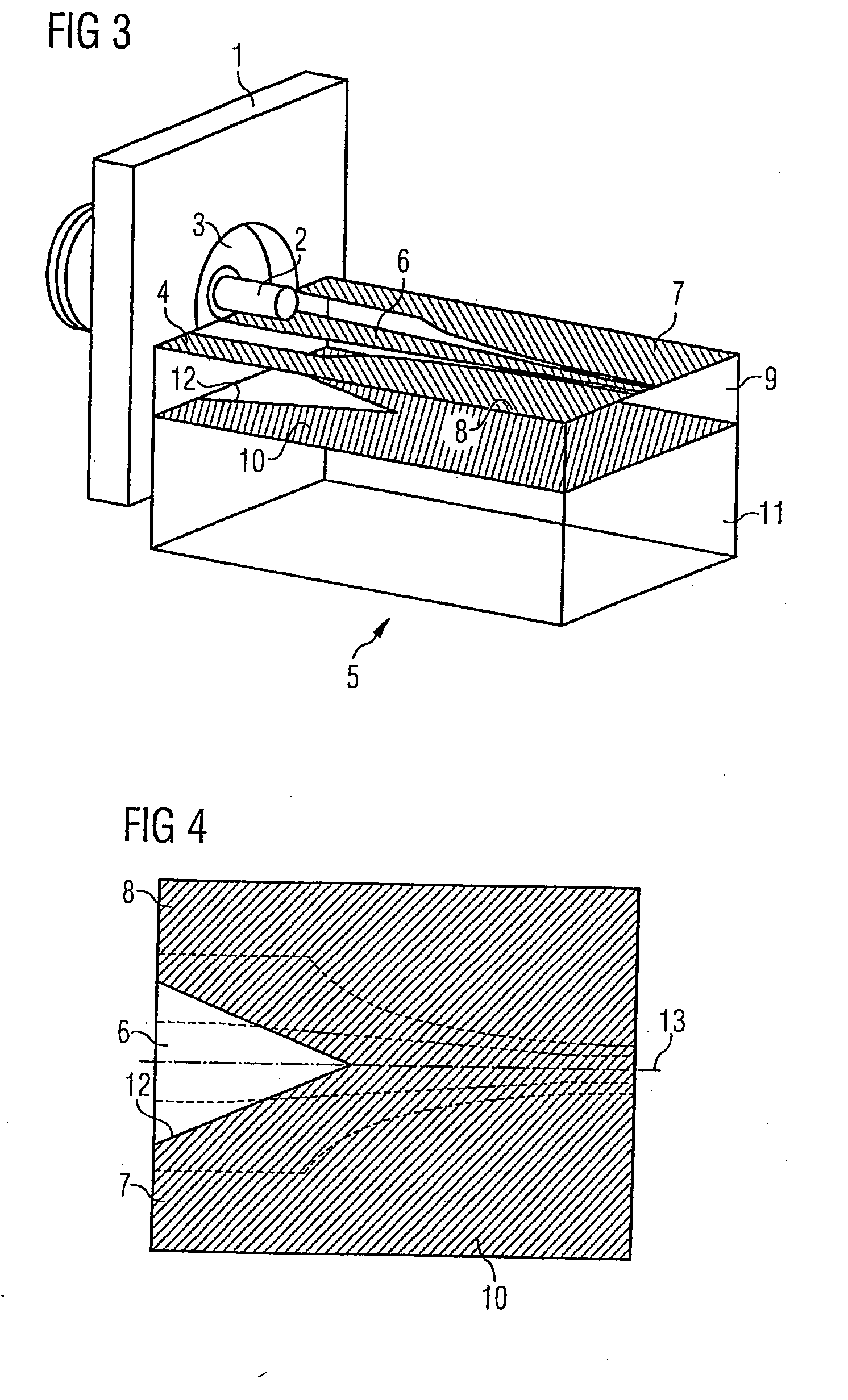
[0022]FIG. 3 shows, for instance, an embodiment of a device for connecting a coaxial line to a coplanar line, in particular for connecting a coaxial plug 1 to a coplanar line 5 for the transmission of high bit rate data signals. The coaxial line is shown in FIG. 3 for instance by the coaxial plug 1 and comprises, in a similar manner to the embodiment shown in FIG. 1, a coaxial inner conductor 2, a first dielectric layer 3 and a coaxial outer conductor 4. The coplanar line 5 consists of a conductor layer (6, 7, 8), followed by a second dielectric layer 9, a metallization layer 10 and a substrate carrier layer 11. The conductor layer (6, 7, 8) consists of a coplanar inner conductor 6 and a first and a second coplanar outer conductor 7, 8, the first and second coplanar outer conductor 7, 8 being separated from the coplanar inner conductor 6 by the second dielectric layer 9, for instance. The coaxial inner conductor 2 of the coaxial plug 1 is connected to the coplanar inner conductor 6 ...


PUM


Abstract

The coaxial line comprises a coaxial inner conductor and a first dielectric layer encompassing the coaxial inner conductor and which is surrounded by a coaxial outer conductor. The coplanar line comprises a second dielectric layer with a coplanar inner conductor and a first and second coplanar outer conductor applied to the front side thereof and with a metallization layer followed by a substrate carrier layer on the rear side thereof. The first and second coplanar outer conductors are separated from the coplanar inner conductor by the second dielectric layer and the coaxial inner conductor is connected to the coplanar inner conductor and the coaxial outer conductor is connected to the first and second coplanar outer conductors. When high bit rate data signals are transmitted via the connecting point of the coaxial line and the coplanar line, the capacitative power is increased and undesirable reflections occur. In order to avoid this, a recess is provided in the metallization layer, beginning at the point of connection between the coaxial line and the coplanar line and extending in an approximately symmetrical manner with respect to the coplanar inner conductor, tapering in the direction of the coplanar inner conductor as the distance from the point of connection increases.

Description

CROSS REFERENCE TO RELATED APPLICATIONS [0001] This application is the US National Stage of International Application No. PCT / EP2004 / 052322, filed Sep. 27, 2004 and claims the benefit thereof. The International Application claims the benefits of German application No. 10345218.4 filed Sep. 29, 2003, both of the applications are incorporated by reference herein in their entirety.FIELD OF THE INVENTION [0002] The invention relates to a device for connecting a coaxial line to a coplanar line for the transmission of high bit rate data signals, wherein the coaxial line comprises a coaxial inner conductor and a first dielectric layer encompassing the coaxial inner conductor, the dielectric layer being surrounded by a coaxial outer conductor. The coplanar line comprises a second dielectric layer, applied to the front face of which are a coplanar inner conductor and a first and second coplanar outer conductor, and the rear face of which comprises a metallization layer followed by a substrat...

Claims


Application Information

Patent Timeline
Patent Type & Authority Applications(United States)
IPC IPC(8): H03H7/38H01P5/08H01R13/646
CPCH01P5/085H01R2103/00H01R24/50H01R24/44
Inventor WEISKE, CLAUS-JORG
Owner SIEMENS AG
Why Eureka
Try Eureka