Performance monitoring of frame transmission in data network oam protocols

Inactive Publication Date: 2006-12-21
RPX CORP
View PDF5 Cites 216 Cited by
  • Summary
  • Abstract
  • Description
  • Claims
  • Application Information

AI Technical Summary

Benefits of technology

[0102] The present invention provides significant advantages over the prior art. First, it can be easily implemented within the existing OAM framework, and can share hardware already used for the OAM functions. This makes the invention easy to manage for operators and providers. Second, the solution can use randomizations to ensure better statistical significance of layer-2 measurements. A layer-2 driver is likely to run much closer (if not directly in) the network card than a layer-3 processing module, thus obtaining better estimates of the real sending times Oust before the first bit is sent) and reception times Oust after the last bit is received). While these errors can be compensated by calibration, it is still best to minimize or avoid them altogether.
[0103] Third, the invention does not need a signaling protocol whereby the nodes in the MA are informed of the parameters of the measurement session; the interval ID allows a source to initiate the equivalent of a session, without establishing an actual session, therefore the performance mo

Problems solved by technology

While network performance measuring at layers 3 and above, with limited accuracy, was previously sufficient, more accuracy is currently needed.
Active solutions are usually preferred, since they are much easier to deploy, although they are inherently less accurate because they inject extra traffic into the same network that they are measuring.
A problem with using counters is that local counters do not provide the basis for a measurement of Delays or Delay Variations.
In the measurement of Losses, there needs to be an exchange of counter information between a sending node and a receiving node in order to correlate between the observed frames, which adds a layer of complexity to the measurement.
The methodological approach from IETF's IPPM

Method used


Image

  • Performance monitoring of frame transmission in data network oam protocols
  • Performance monitoring of frame transmission in data network oam protocols
  • Performance monitoring of frame transmission in data network oam protocols

Examples


Embodiment Construction

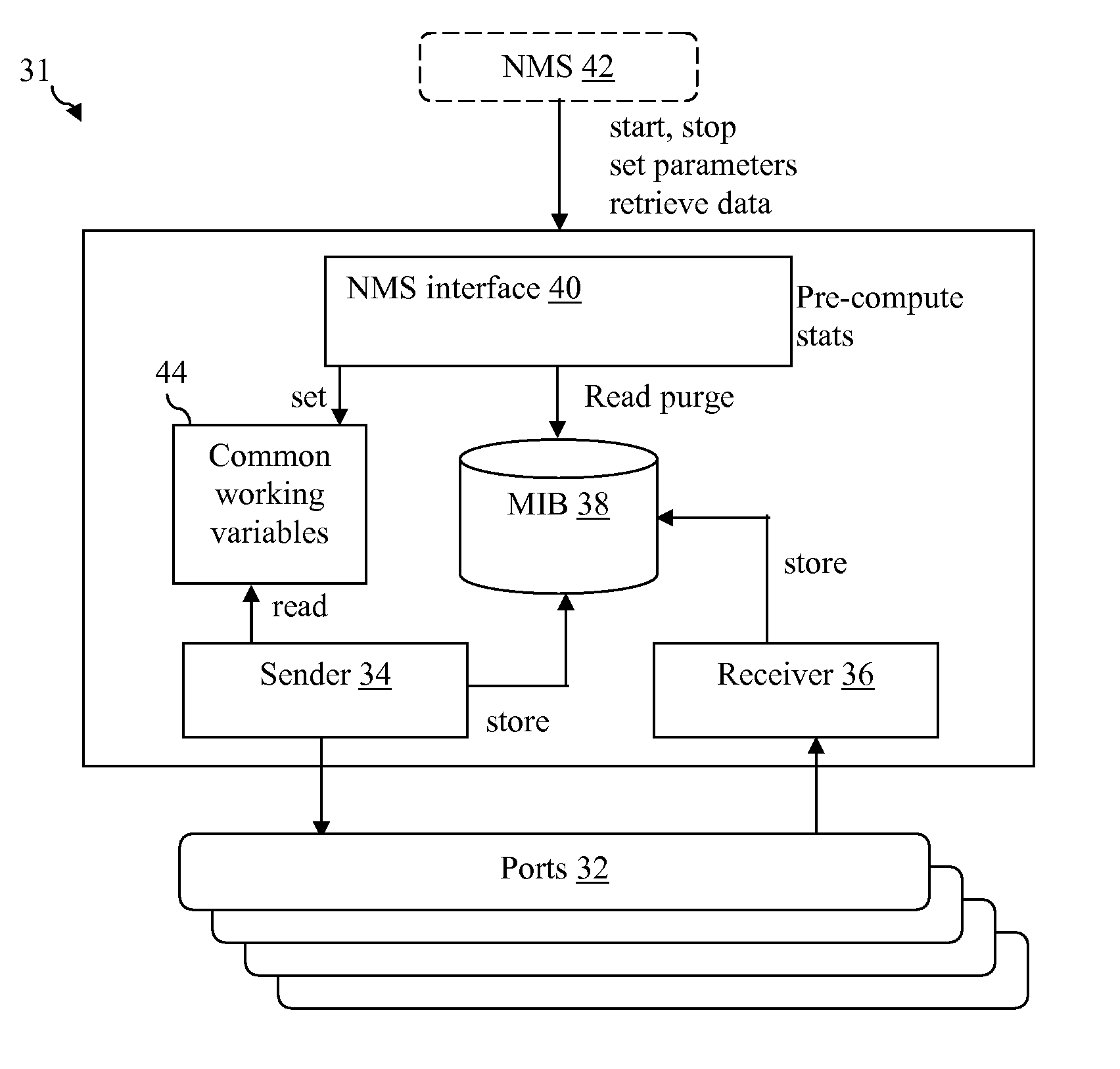
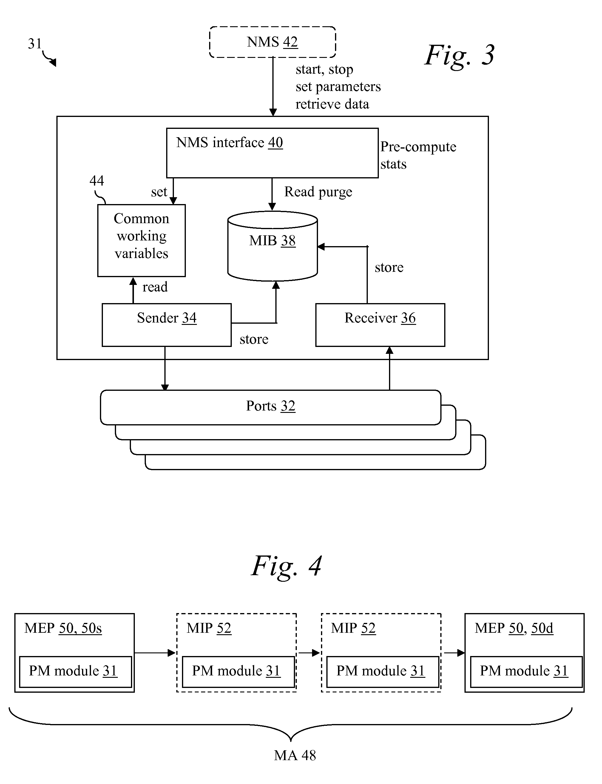
[0026] The present invention is best understood in relation to FIGS. 1-8 of the drawings, like numerals being used for like elements of the various drawings.

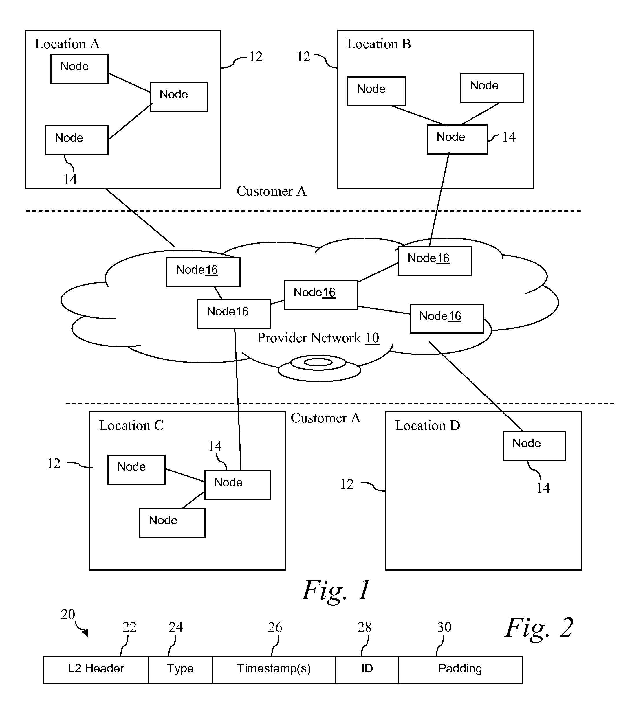
[0027]FIG. 1 illustrates a very simplified diagram of an environment in which the present invention could be used. A provider network 10 links one or more locations of a customer network. In the illustrated embodiment, the customer network is shown having four locations (illustrated individually Locations A, B, C and D), each having its own local network 12. Edge nodes 14 provide a connection between the local area networks 12 and the provider nodes 16 of the provider network 10. The provider network 10 thus connects the various local networks 12 to form a wide area network.

[0028] In an actual implementation, the provider network 10 could support multiple customers, and it may use additional third party provider networks to provide the necessary connectivity.

[0029] Presently, situations such as that described above provide a ...


PUM


Abstract

Performance measurements for a network, such as delay, delay variation, and loss, are performed over layer-2. A PM frame is sent from a source MEP (Maintenance End Point) to a destination MEP. The PM frame is timestamped immediately prior to transmission, and the local clock at the destination MEP is noted immediately upon arrival. MIPs (Maintenance Intermediate Points) may also time stamp the PM frame. Preferably, each PM frame has an interval (session) identifier and a sequence number within the interval. The PM frames are received by and sent by PM modules within the nodes of the network. The PM modules include a Sender function for sending an interval of one or more PM frames and a Receiver function for receiving PM frames and computing measurements.

Description

CROSS-REFERENCE TO RELATED APPLICATIONS [0001] This application claims the benefit of the filing date of copending provisional application U.S. Ser. No. 60 / 691,493, filed Jun. 17, 2005, entitled “PERFORMANCE MONITORING OF FRAME TRANSMISSION IN DATA NETWORK OAM PROTOCOLS”.STATEMENT OF FEDERALLY SPONSORED RESEARCH OR DEVELOPMENT [0002] Not Applicable BACKGROUND OF THE INVENTION [0003] 1. Technical Field [0004] This invention relates in general to data communications and, more particularly, to performance monitoring of frame transmission in a data network. [0005] 2. Description of the Related Art [0006] There is a growing demand for network performance monitoring in data network. Until recently, this network performance monitoring was used mostly for network troubleshooting (network management, status and alarms) in addition to usual methods of connectivity tests. Now, it is also needed for SLA (Service Level Agreement) checking, billing, and network security (flood attack detection, e...

Claims


Application Information

Patent Timeline
IPC IPC(8): H04J1/16
CPCH04L41/142H04L2012/5649H04L41/5087H04L41/509H04L43/067H04L43/0858H04L43/106H04L45/50H04L47/11H04L47/20H04L47/2425H04L47/283H04L2012/5625H04L2012/5636H04L41/5006
Inventor DAMM, GERARD
Owner RPX CORP
Why Eureka
Try Eureka