
Device for medical provision

Active Publication Date: 2006-12-21
SIEMENS HEALTHCARE GMBH
View PDF5 Cites 14 Cited by
  • Summary
  • Abstract
  • Description
  • Claims
  • Application Information

AI Technical Summary

Benefits of technology

[0014] This embodiment offers the advantage of effectively preventing incorrect control of the movement of the medical functional unit. This is because a movement of the guidance element which would lead to a collision between the medical functional unit and an obstacle can be suppressed by the inhibiting device. In addition the danger of a collision can be intuitively communicated to the user.
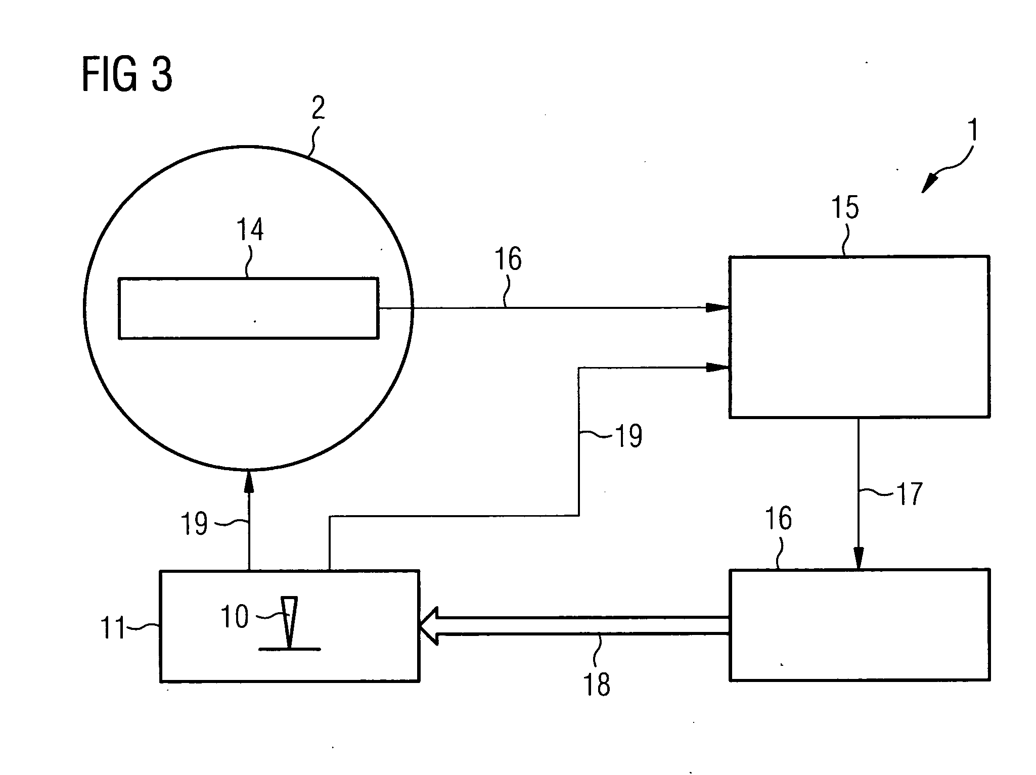
[0015] To allow the warning signal to be output at an early stage before or during the movement of the medical functional unit, in addition to a position signal from the position sensor, a control signal from the guidance device is applied to the monitoring unit. This makes it possible before or during the movement of the medical functional unit to restrict the movement and thereby to prevent a collision of the medical functional unit with an obstacle.
[0017] Furthermore the guidance element is preferably a joystick which can be operated manually. Complex movements can be controlled with this type of joystick. In addition a control device can operate a joystick mechanically in a simple manner.

Problems solved by technology

One disadvantage of the known device is that optical signals can easily be overlooked since the user also has to take account of other optical information communicated during the movement of the C-arm.
In addition the patient becomes restless, generally assuming that a malfunction has occurred.

Method used


Image

  • Device for medical provision
  • Device for medical provision
  • Device for medical provision

Examples


Embodiment Construction

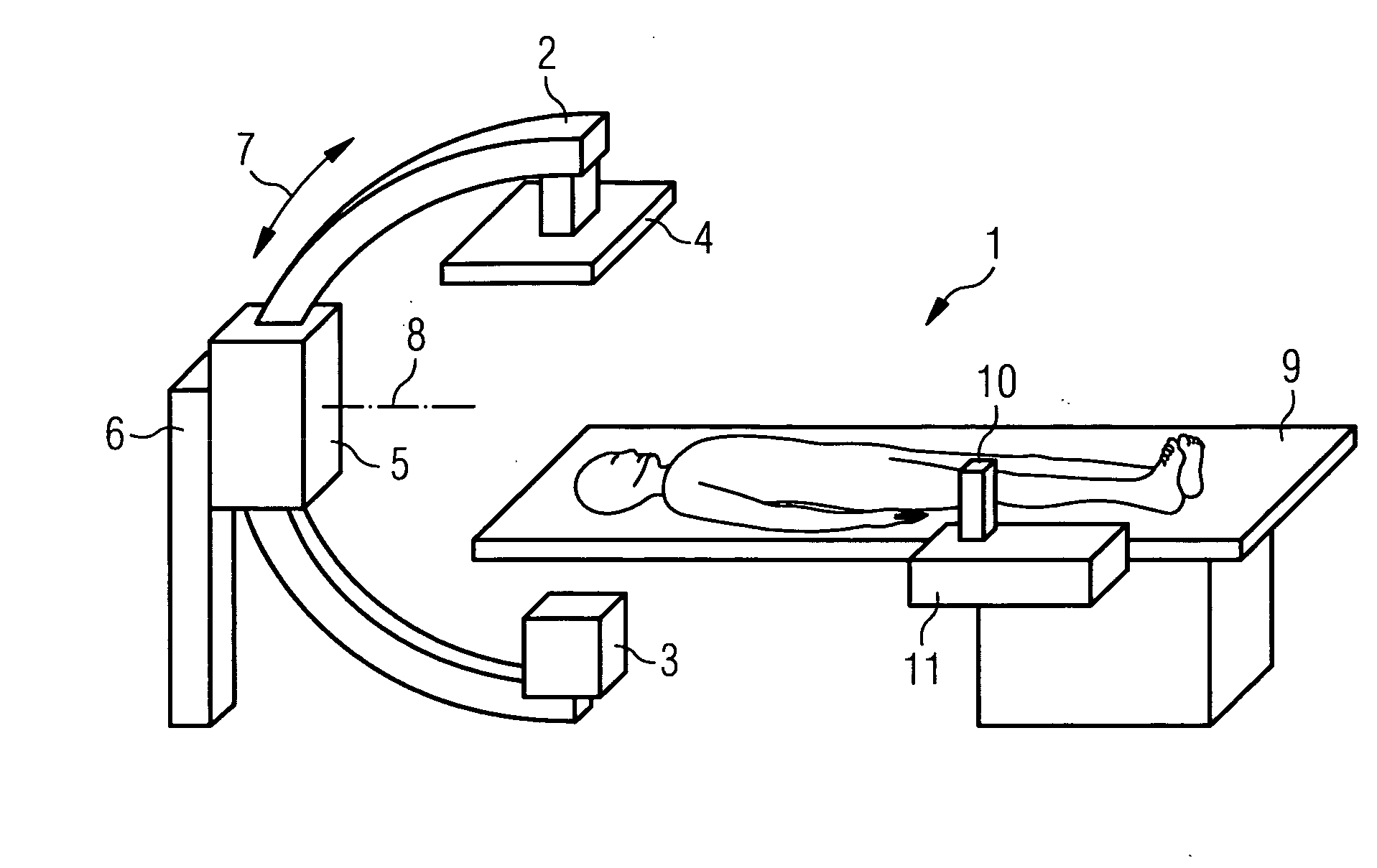
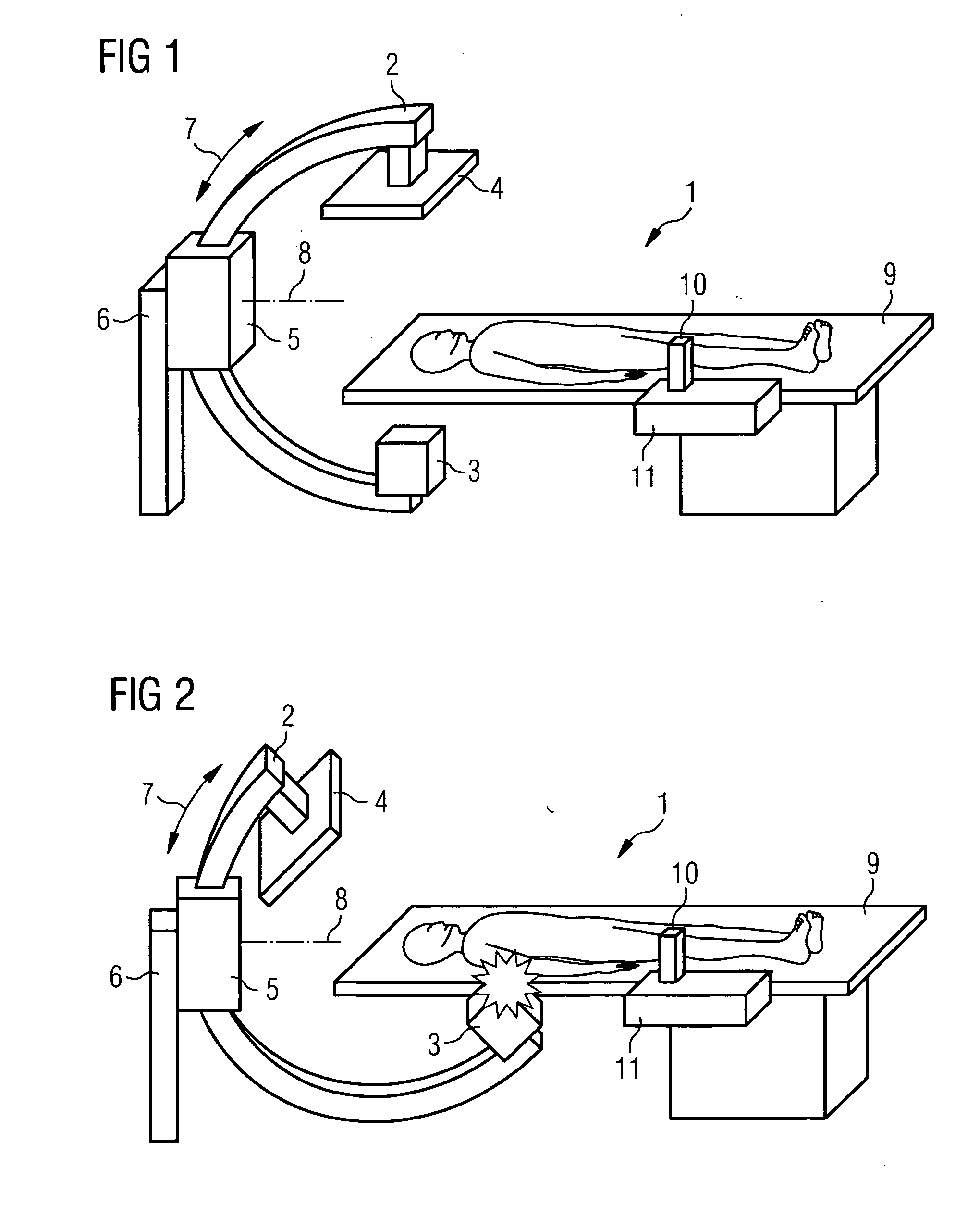
[0022] The x-ray system 1 comprises a C-shaped x-ray arm 2, on the ends of which an x-ray source 3 and an x-ray detector 4 are mounted. The x-ray arm 2 is held by a support 5 which is mounted on a stand 6 The x-ray arm 2 can be moved in the support 5 in a circular direction 7. Furthermore the support 5 is mounted on the stand 6 so that it can pivot around an axis 8. Finally the stand 6 can also be moved around the floor.

[0023] During operation of the x-ray system 1 the x-ray arm 2 is both moved in the circular direction 7 and also rotated around the pivot axis 8. In this case the x-ray arm 2 executes a relative movement in relation to a patient bed 9. The x-ray arm 2 is controlled amongst other methods with the aid of a joystick 10 of a guidance device 11. For example the x-ray arm 2 will always move in the circular direction 7 if the joystick 10 is pushed to the left or to the right. In this case the x-ray arm 2 performs a rotational movement if the joystick 10 is pushed forwards ...


PUM


Abstract

An x-ray arm of an x-ray system is controlled with the aid of a joystick. If there is a threat of a collision between the x-ray arm and an obstacle, for example a patient bed, a force is exerted on the guide element which generates a warning signal perceptible in a tactile manner, which indicates to the user the danger of a collision.

Description

CROSS REFERENCE TO RELATED APPLICATIONS [0001] This application claims the benefits of German Patent application No. 10 2005 028 215.6 filed Jun. 17, 2005 and is incorporated by reference herein in its entirety. FIELD OF THE INVENTION [0002] The invention relates to a device for medical provision of a patient with: [0003] a medical functional unit which can be controlled by a user and is moveable in relation to a patient bed, [0004] a position sensor, which detects the position of the functional unit, and with [0005] a monitoring device connected downstream from the position sensor which monitors the movement of the functional unit and, if there is a danger of a collision with an obstacle, generates a warning signal perceptible to the user. BACKGROUND OF THE INVENTION [0006] Such a device is known from DE 36 04 955 C2. The known device is an x-ray diagnostic device which features a moveable C-arm on the ends of which an x-ray detector and an x-ray emitter respectively are mounted. T...

Claims


Application Information

Patent Timeline
IPC IPC(8): H05G1/54
CPCA61B6/102
Inventor CAMUS, ESTELLE
Owner SIEMENS HEALTHCARE GMBH
Learn More