

Phase Matched Optical Grating
- Summary
- Abstract
- Description
- Claims
- Application Information
AI Technical Summary
Benefits of technology
Problems solved by technology
Method used
Image

Examples
Embodiment Construction
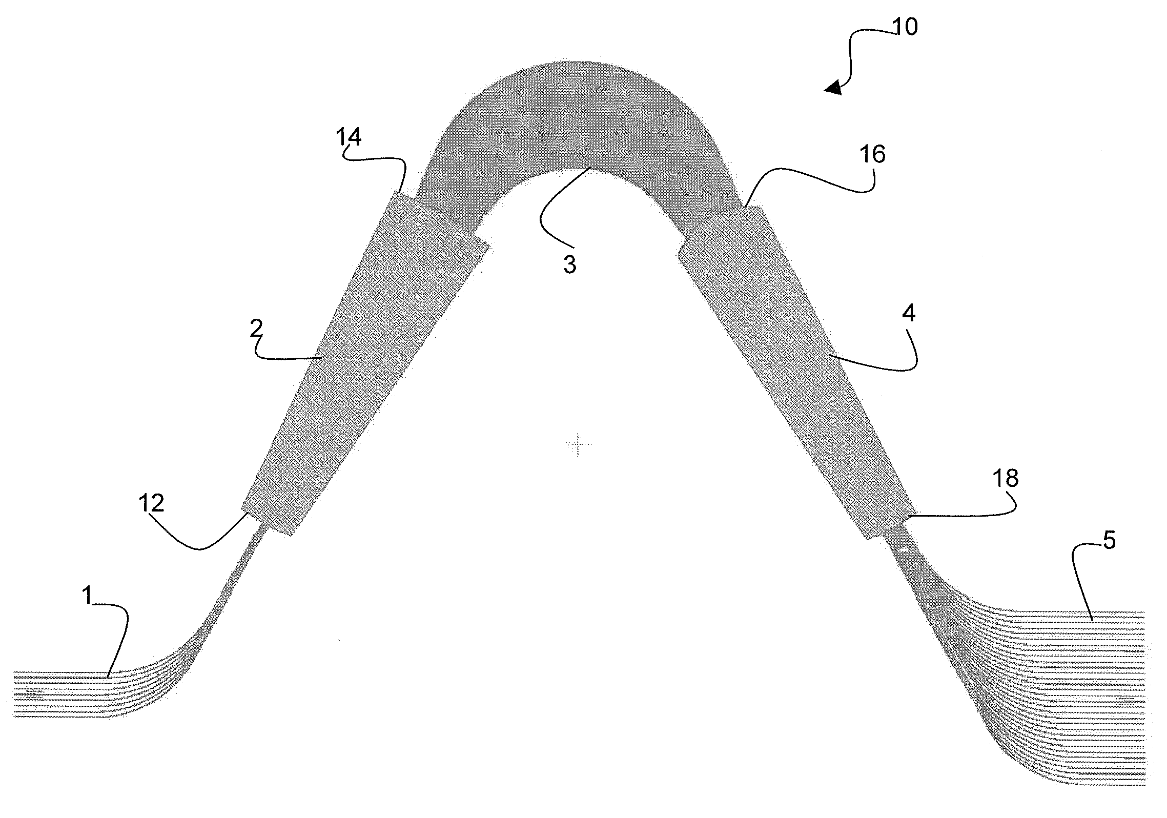
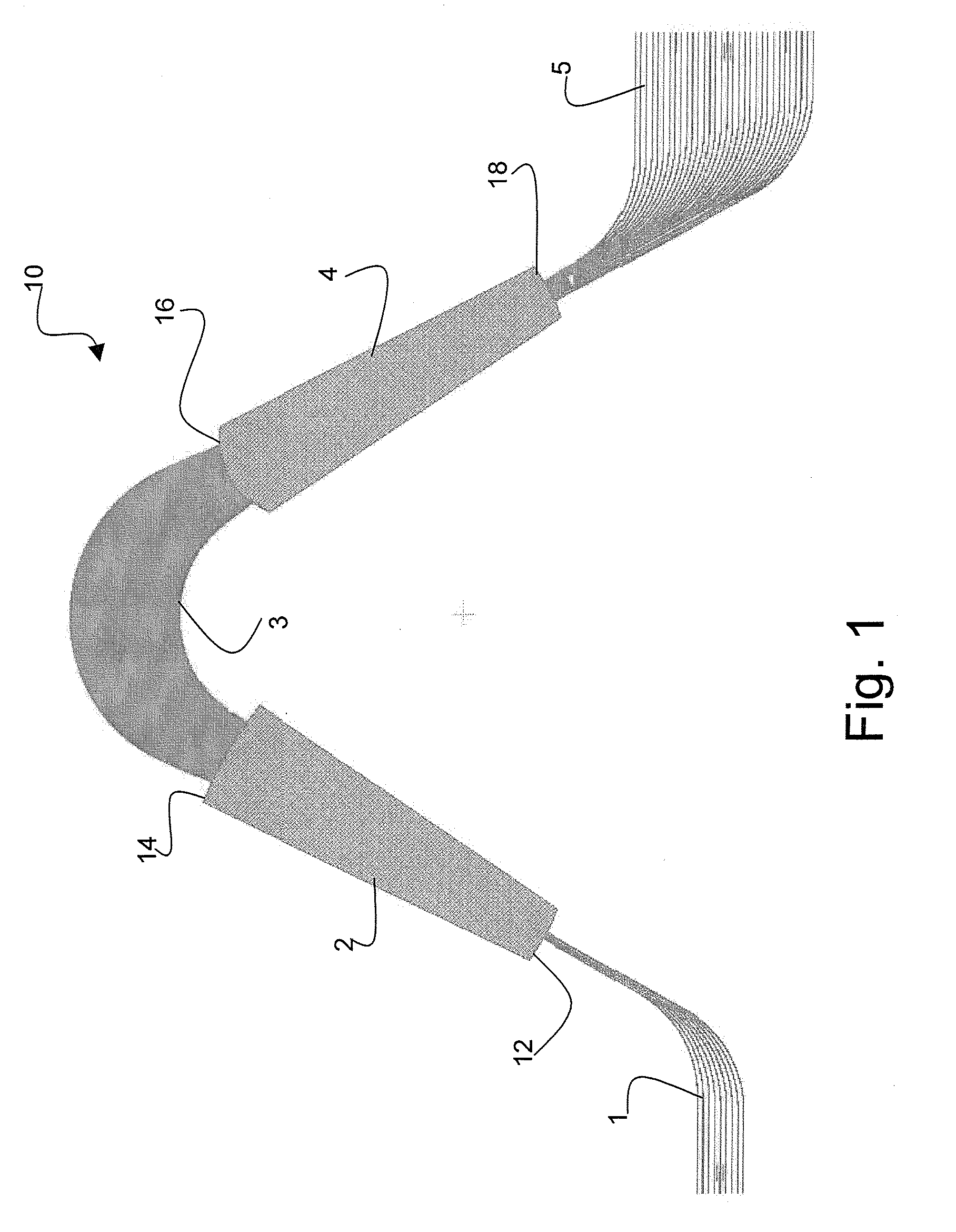
[0039] With reference to FIG. 1, an arrayed waveguide grating AWG is shown generally at 10, in accordance with the present invention, consisting of an input waveguide 1 optically coupled to an input star coupler 2 at an input focal line 12. The input star coupler 2 is optically coupled to an array of waveguide arms 3 at an input grating line 14. The array of waveguide arms 3 is optically coupled to an output star coupler 4 at an elliptical output grating line 16. Light from the array of waveguide arms 3 is transmitted across the output star coupler 4 to a plurality of output waveguides 5 arranged on an output focal line 18.
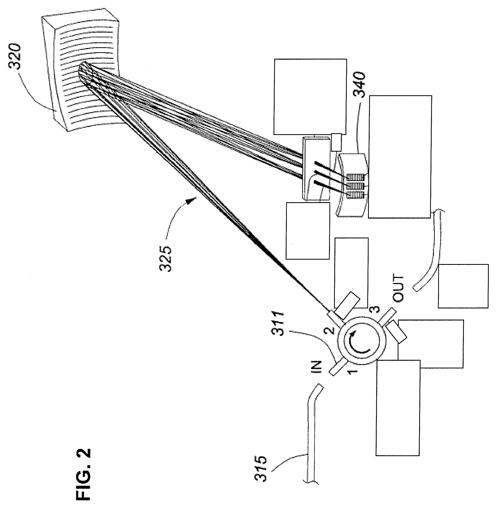
[0040]FIG. 2 illustrates a diffraction grating multiplexer shown generally at 325. A WDM signal comprising light having a plurality of wavelengths is coupled from waveguide 315 into a circulator 311 at port 1 and directed from output port 2 toward the concave diffraction grating 320. Grating 320 has an ellipsoid profile to modify the phase of the dispersed output...
PUM
 Abstract
Description
Claims
Application Information