Electromotive drive module

a drive module and electric motor technology, applied in the direction of engine-driven generator propulsion, mechanical equipment, transportation and packaging, etc., can solve the problems of large modification and development work in association with massive changes to existing systems, and still standconsiderable cost problems, so as to save considerable assembly time and cost, and reduce costs. the effect of cos

Inactive Publication Date: 2006-12-28
ZF FRIEDRICHSHAFEN AG
View PDF7 Cites 110 Cited by
  • Summary
  • Abstract
  • Description
  • Claims
  • Application Information

AI Technical Summary

Benefits of technology

[0006] According to the invention, an electromotive drive module represents a structural unit which includes the electric machine and two clutches and which is designed specifically to be installed in the vehicle's powertrain. With the help of the clutches, the rotor of the electric machine can be connected as desired either to the internal combustion engine, to the transmission, or to both the internal combustion engine and the transmission for the transmission of torque. A module of this type can be manufactured by a supplier, fo

Problems solved by technology

Fundamental technical problems of integrating electric drives into motor vehicle powertrains have already been solved, but considerable cost problems still stand in the way of customer acceptance and thus of rapid market introduction.
These cost problems are attributable at least in part to the

Method used


Image

  • Electromotive drive module
  • Electromotive drive module
  • Electromotive drive module

Examples


Embodiment Construction

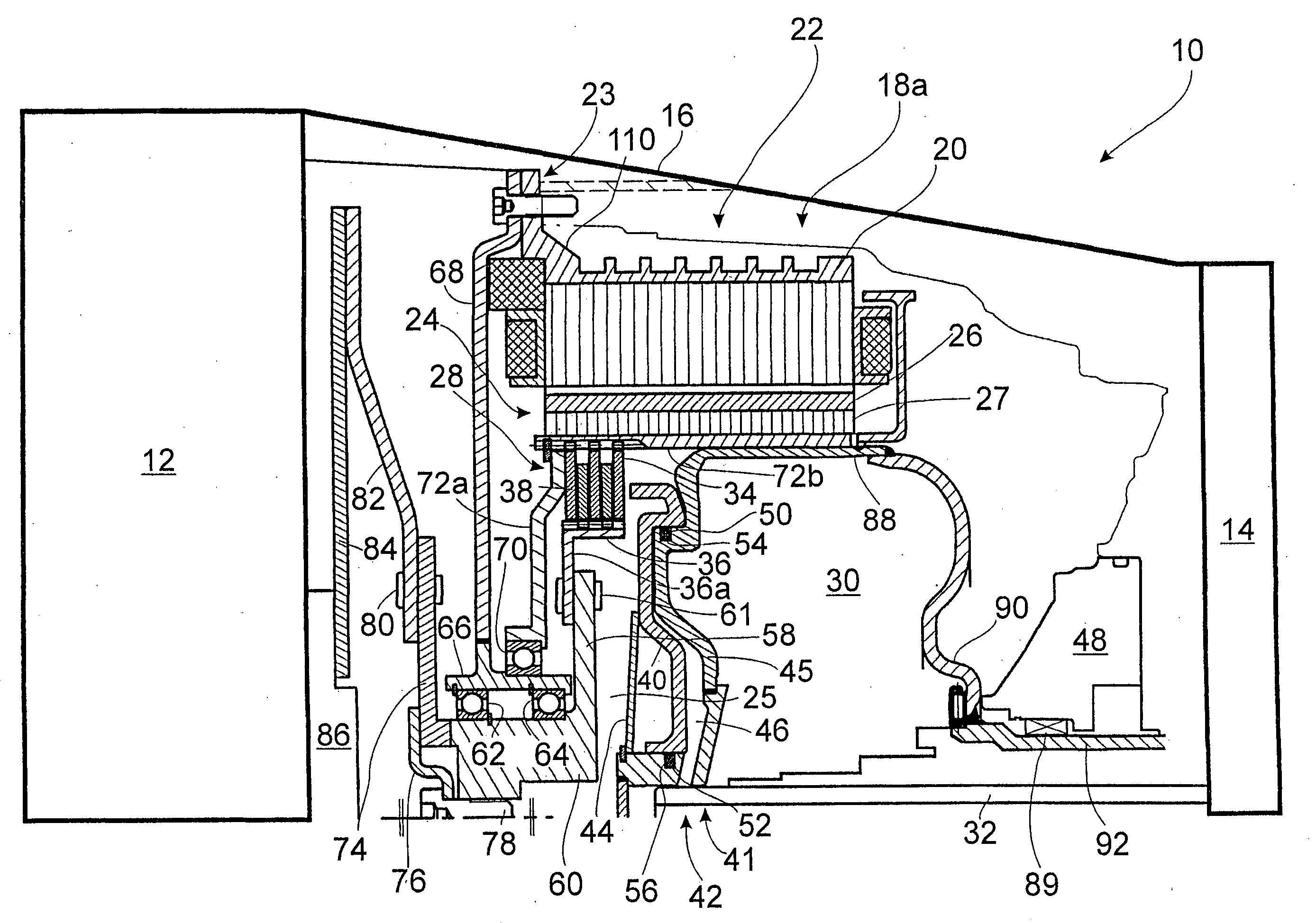
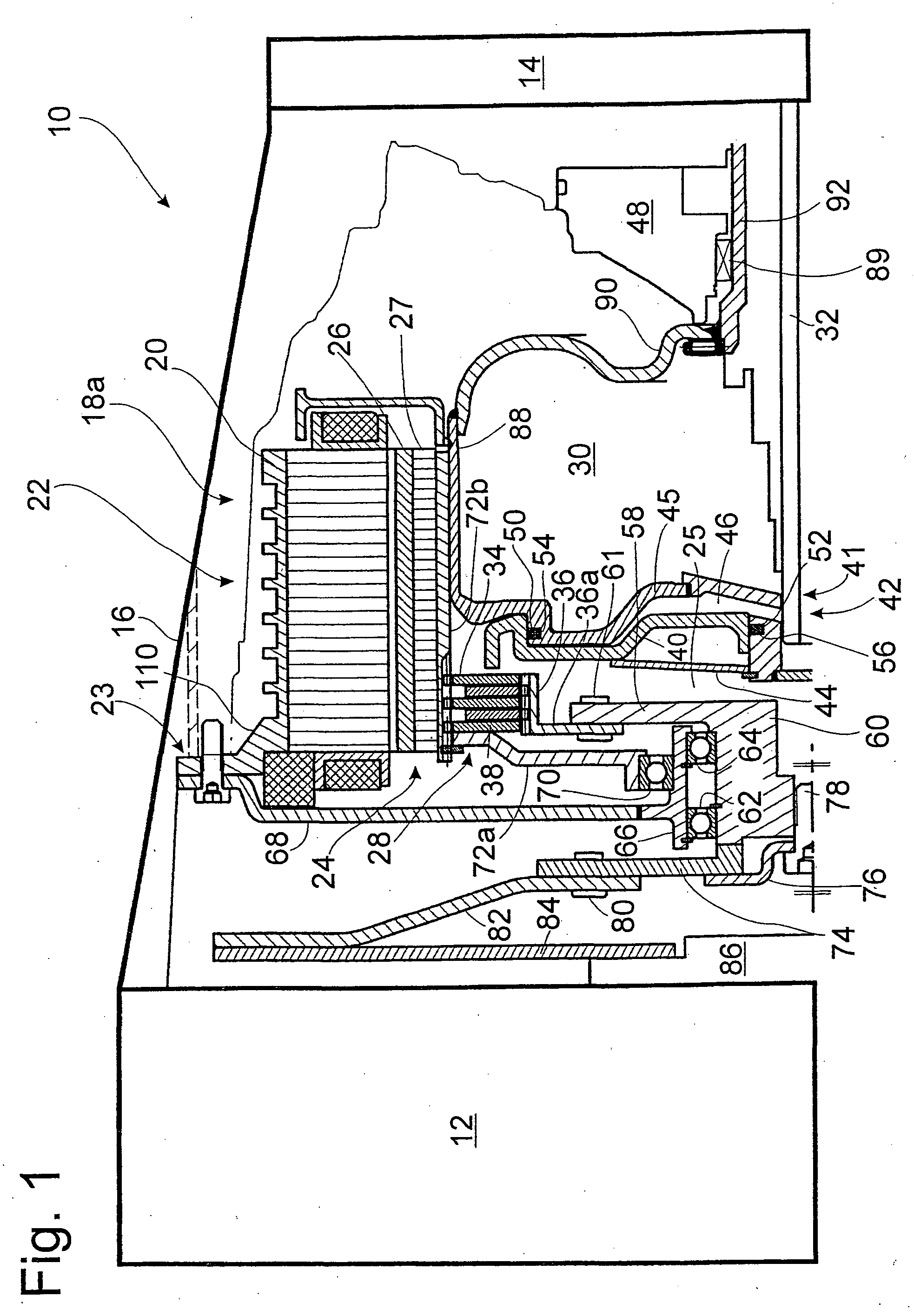
[0017]FIG. 1 is a partially schematized axial cross section of part of a conventional motor vehicle powertrain 10, originally of the conventional type from series production with an internal combustion engine 12 and a gear-shift transmission 14, which is designed here as an automatic transmission. The space present in the transmission bell housing 16 between the internal combustion engine 12 and the transmission 14 is usually reserved for a friction clutch or, in the housing of an automatic transmission, for a hydrodynamic torque converter serving as a start-up element.

[0018] It can be seen that, instead of the friction clutch or torque converter, an electromotive drive module 18a has been integrated into the powertrain inside the transmission bell housing 16, so that the vehicle can be driven as needed either purely by the electric motor, purely by the internal combustion engine, or by a combination of the two. For this purpose, the stator 20 of an electric machine 22 of the inter...


PUM


Abstract

An electromotive drive module for installation in a housing between an internal combustion engine and a transmission of a motor vehicle power train. The drive module includes an electric machine with a stator and a rotor and first and second clutch devices, by means of which the rotor can be connected when desired to the internal combustion engine and/or to the transmission for the transmission of torque.

Description

BACKGROUND OF THE INVENTION [0001] 1. Field of the Invention [0002] The invention pertains to an electromotive drive module for installation in a motor vehicle powertrain with an internal combustion engine and a transmission. [0003] 2. Description of the Related Art [0004] It is well known that the integration of one or more electric machines into the powertrain of a motor vehicle and the realization of purely electric powertrains and of hybrid powertrains combining an electric motor with an internal combustion engine have been a long-term development goal of the automotive industry for many years. The efforts in this direction have intensified especially in recent years because of the continuous increase in the cost of fuel and the demand to reduce the pollution caused by internal combustion engines. Fundamental technical problems of integrating electric drives into motor vehicle powertrains have already been solved, but considerable cost problems still stand in the way of customer...

Claims


Application Information

Patent Timeline
IPC IPC(8): B60K6/02B60K6/26B60K6/387B60K6/405B60K6/48
CPCB60K6/26B60K6/387Y02T10/6221B60K6/48F16D25/0638B60K6/405B60L50/16Y02T10/62Y02T10/7072Y02T10/70
Inventor GROSSPIETSCH, WOLFGANGSUDAU, JORGHERBST, RUDIGERKLEUKER, CHRISTOPHZIMMER, MANFREDBUSOLD, THOMASMATSCHAS, STEFFENMULLER, THORSTEN
Owner ZF FRIEDRICHSHAFEN AG
Why Eureka
Try Eureka