Method and apparatus for performing hydrogen optical emission endpoint detection for photoresist strip and residue removal

a photoresist strip and endpoint detection technology, applied in the direction of fluid pressure measurement, instruments, vacuum gauges, etc., can solve the problems of non-uniform vertical removal (stripping) of the photoresist strip, non-uniform removal, and substantial post-implant residue remaining on the substra

Inactive Publication Date: 2006-12-28
APPLIED MATERIALS INC
View PDF20 Cites 99 Cited by
  • Summary
  • Abstract
  • Description
  • Claims
  • Application Information

AI Technical Summary

Problems solved by technology

This makes the characteristics of the photoresist material vertically non-uniform such that uniform removal (stripping) of the photoresist can be difficult.
As such, the photoresist removal process may result in non-uniform removal and substantial post-implant residue remaining on the substrate.
However, such an endpoint detection technique does not account for the variations in the characteristics of a photoresist layer that has been exposed to an ion beam.

Method used


Image

  • Method and apparatus for performing hydrogen optical emission endpoint detection for photoresist strip and residue removal
  • Method and apparatus for performing hydrogen optical emission endpoint detection for photoresist strip and residue removal
  • Method and apparatus for performing hydrogen optical emission endpoint detection for photoresist strip and residue removal

Examples


Embodiment Construction

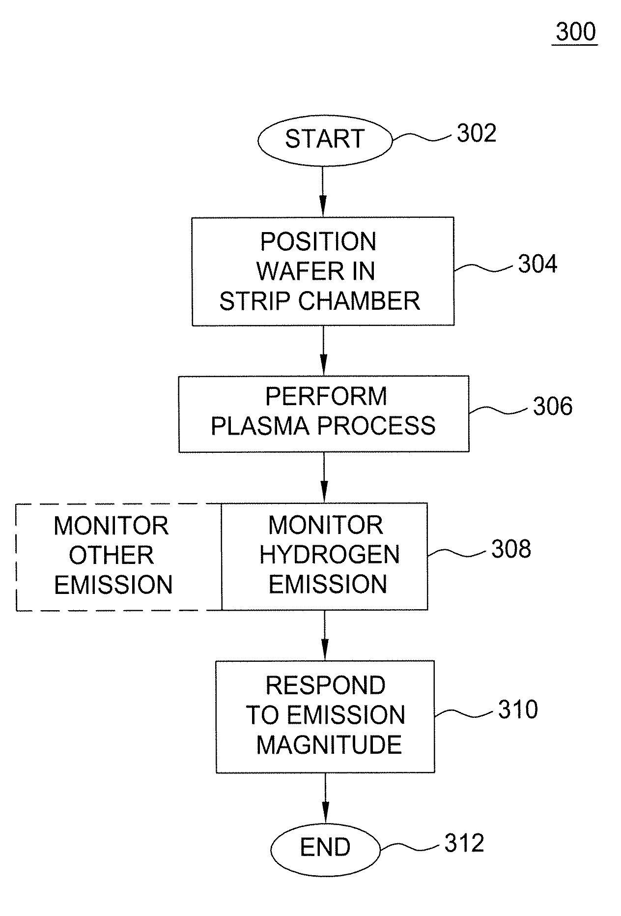
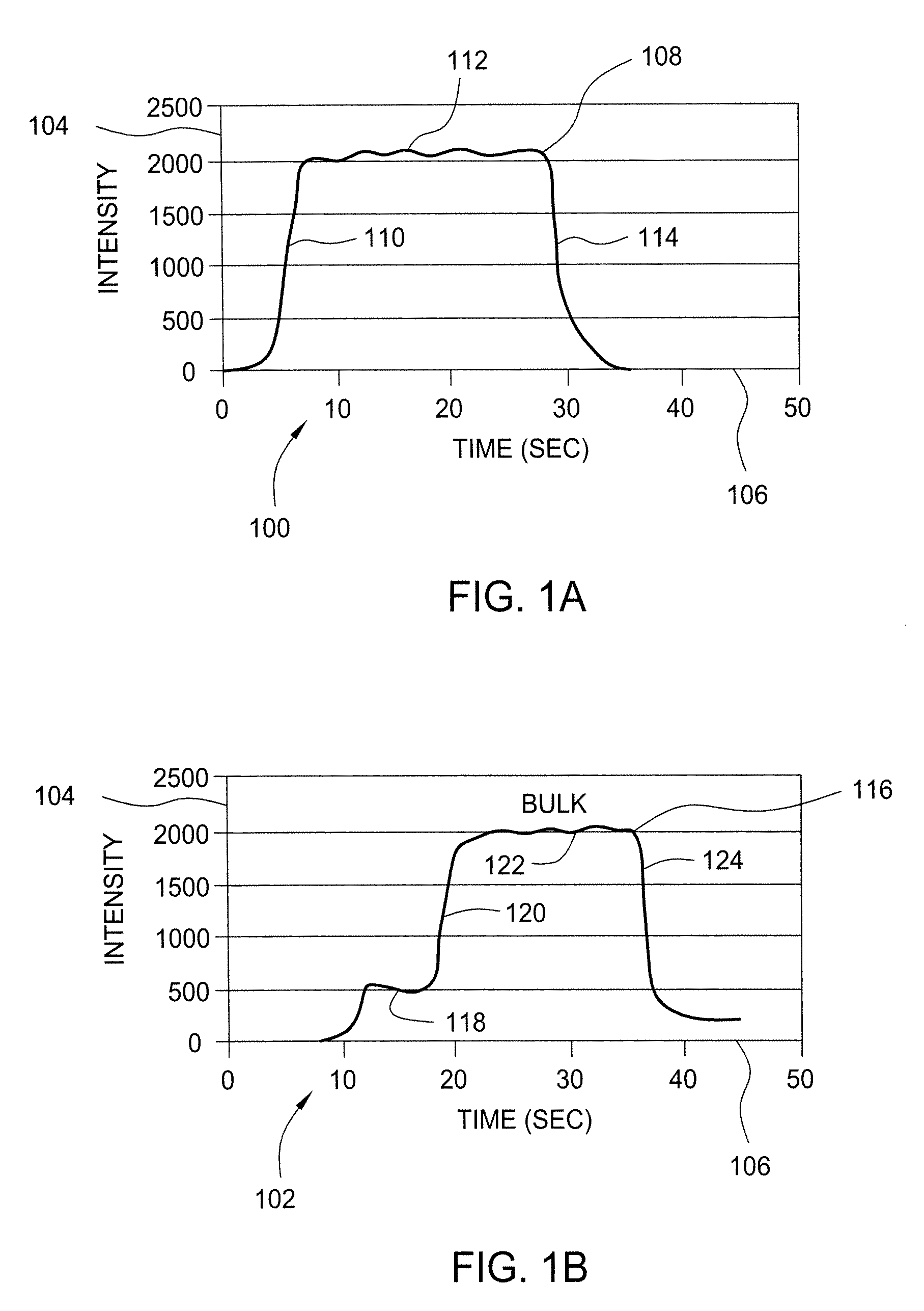
[0018] The invention relates to a method for monitoring and detecting optical emission endpoint(s), more particularly hydrogen emissions, for photoresist stripping and removal of residues from a substrate or a film stack on a substrate. In one embodiment of the invention, a method determines and uses a hydrogen optical emission peak for identifying an endpoint of a photoresist stripping process, including blanket and patterned photoresist, post-implant photoresist, and post-plasma etch photoresist. In addition, the invention comprises a method to use optical emission endpoint in general, and hydrogen peak specifically, to monitor the transition from crust removal to bulk photoresist removal for post-implant stripping. By this method, the hydrogen endpoint trace is a more direct measure of stripping for patterned implant substrates (compared to other peaks such as oxygen).

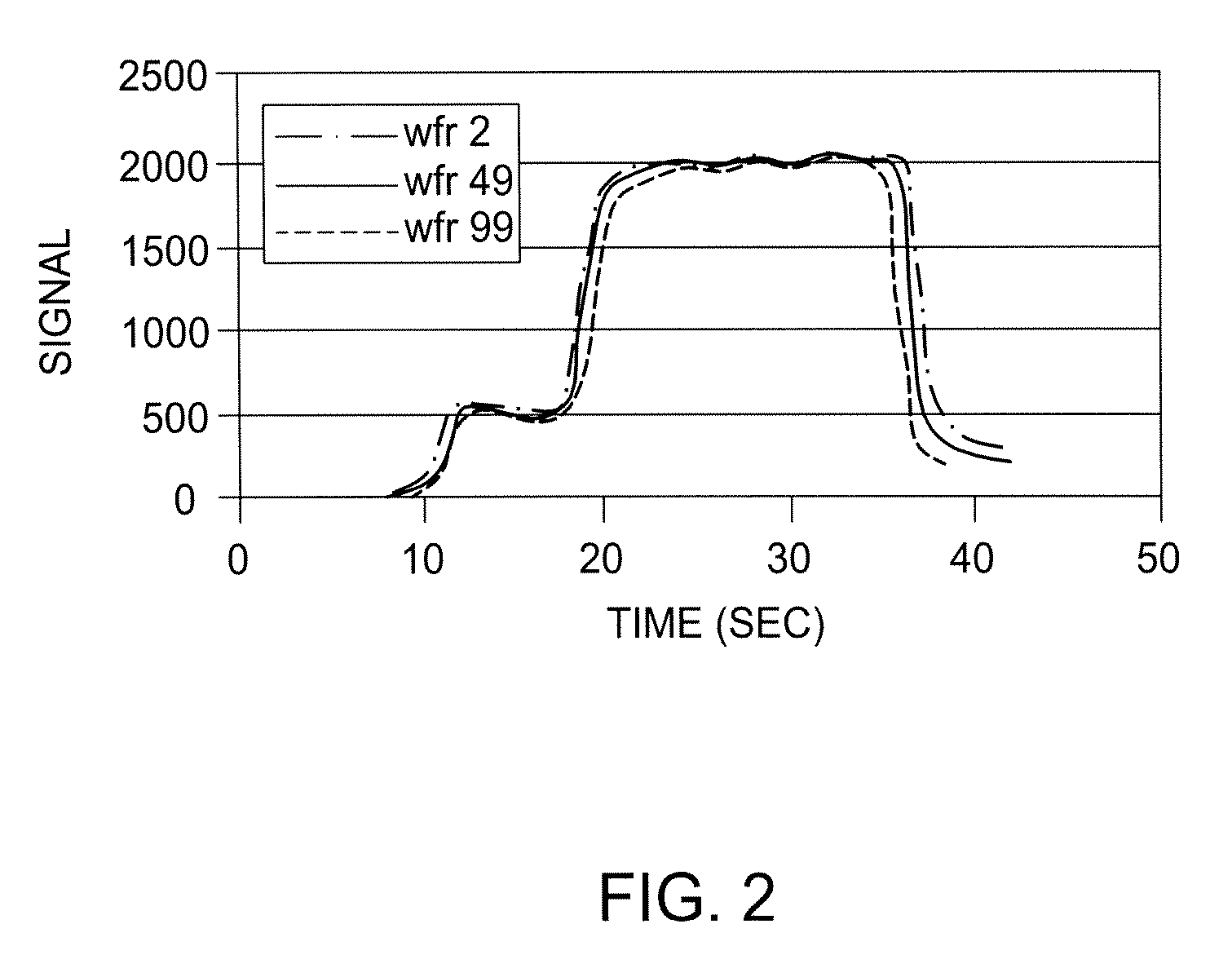
[0019] The present invention uses, in one embodiment, the hydrogen optical emission peak at 656 nm to monitor en...


PUM

PropertyMeasurementUnit
wavelengthaaaaaaaaaa
temperatureaaaaaaaaaa

Abstract

Methods for monitoring and detecting optical emissions while performing photoresist stripping and removal of residues from a substrate or a film stack on a substrate are provided herein. In one embodiment, a method is provided that includes positioning a substrate comprising a photoresist layer into a processing chamber; processing the photoresist layer using a multiple step plasma process; and monitoring the plasma for a hydrogen optical emission during the multiple step plasma process; wherein the multiple step plasma process includes removing a bulk of the photoresist layer using a bulk removal step; and switching to an overetch step in response to the monitored hydrogen optical emission.

Description

CROSS-REFERENCE TO RELATED APPLICATIONS [0001] This application is a continuation of co-pending U.S. patent application Ser. No. 10 / 776,672, filed Feb. 11, 2004, which claims benefit of U.S. provisional patent application Ser. No. 60 / 447,625, filed Feb. 15, 2003. Each of the aforementioned related patent applications is herein incorporated by reference.BACKGROUND OF THE INVENTION [0002] 1. Field of the Invention [0003] The present invention relates generally to a method for semiconductor substrate processing. More specifically, the invention relates to a method for monitoring and detecting optical emission endpoint(s), for photoresist stripping and removal of residues from a substrate or a film stack on a substrate. [0004] 2. Description of the Related Art [0005] As a part of semiconductor manufacturing, various layers of dielectric, semiconducting, and conducting films, such as silicon dioxide, polysilicon, and metal compounds and alloys, are deposited on a silicon substrate. Featu...

Claims


Application Information

Patent Timeline
Patent Type & Authority Applications(United States)
IPC IPC(8): G01L21/30C23F1/00H01L21/302H01J37/32H01L21/306H01L23/00
CPCH01J37/32935H01J2237/3342H01J37/32963
Inventor PAVEL, ELIZABETH G.KAWAGUCHI, MARK N.PAPANU, JAMES S.
Owner APPLIED MATERIALS INC
Why Eureka
Try Eureka