Infrared ray lamp, heating devices and electronic device

a technology of infrared ray lamps and electronic devices, which is applied in the direction of ohmic-resistance waterproof/airtight seals, instruments, furniture, etc., can solve the problems of dust reducing the commercial value of heat generating elements and heat generating elements becoming defective units, etc., and achieves long service life and high reliability of electronic devices. , the effect of high reliability of electronic devices

Inactive Publication Date: 2006-12-28
PANASONIC CORP
View PDF7 Cites 24 Cited by
  • Summary
  • Abstract
  • Description
  • Claims
  • Application Information

AI Technical Summary

Benefits of technology

[0043] In accordance with the present invention, it is possible to achieve a high reliable electronic apparatus having a plurality of modes in which the widths heated by the heating apparatus are different. Further, it is possible to make the electronic apparatus compact at a degree at which the heating apparatus can be made compact.
[0044] The electronic apparatus in accordance with another aspect of the present invention is a copying machine, a facsimile machine, a printer, a printing machine, a fixing apparatus, an adhesion apparatus using a thermosetting adhesive agent, a ticket machine, an automatic ticket checking machine, a paper container manufacturing apparatus or a film heat fusion machine. In accordance with the present invention, it is possible to achieve a high reliable electronic apparatus having a plurality of modes in which the widths heated by the heating apparatus are different.
[0045] In the case that the sintered body including the carbon-based material is used as the heat generating element, a time until reaching a rated t

Problems solved by technology

The chip or the dust reduces a commercial value of the heat generating elemen

Method used


Image

  • Infrared ray lamp, heating devices and electronic device
  • Infrared ray lamp, heating devices and electronic device
  • Infrared ray lamp, heating devices and electronic device

Examples


embodiment 1

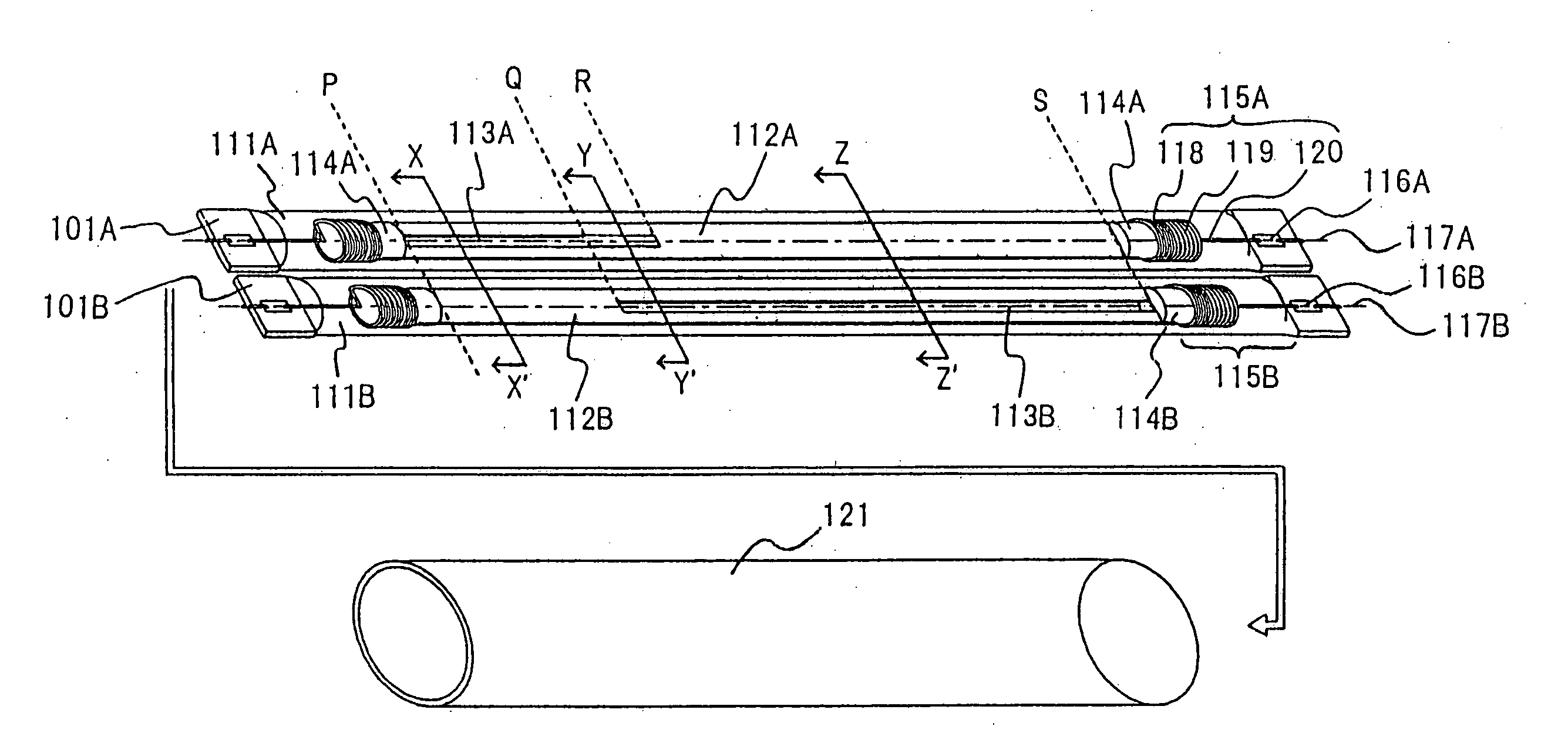
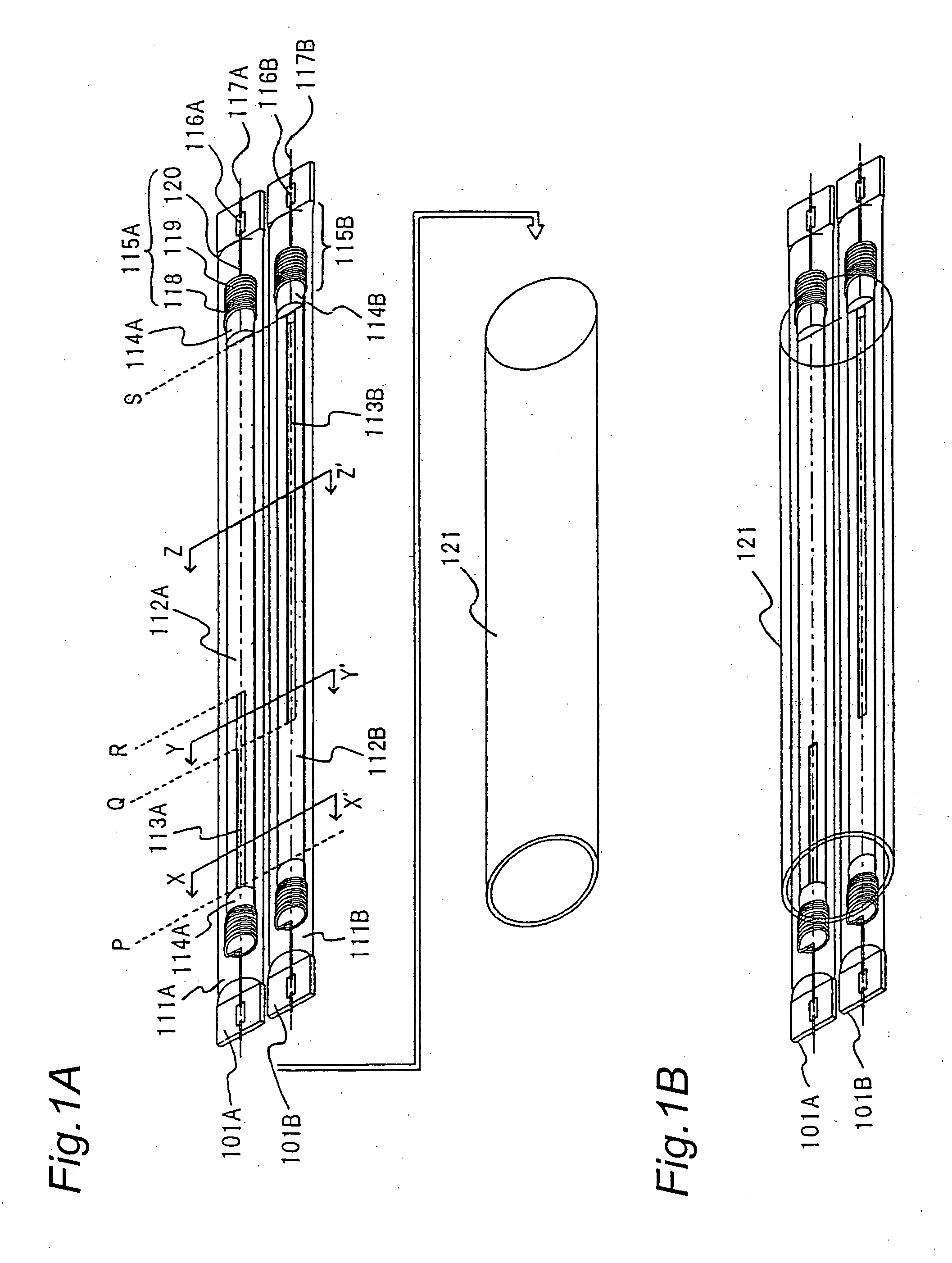
[0067] A description will be given of an infrared ray lamp, a heating apparatus and an electronic apparatus in accordance with an embodiment 1 with reference to FIGS. 1 to 7. FIG. 1 is a view showing a structure of the infrared ray lamp in accordance with the embodiment 1 of the present invention. FIG. 1B is a view showing a state in which two infrared ray lamps shown in FIG. 1A are inserted to a heating roller of a copying machine.

[0068] An infrared ray lamp 101A is formed by sealing a long plate-shaped heat generating element 112A, a holding block 114A and an internal lead wire 115A in a glass tube 11A. In the same manner, the infrared ray lamp 101B is formed by sealing a long plate-shaped heat generating element 112B, a holding block 114B and an internal lead wire 115B in a glass tube 111B. The glass tube 111 is a transparent silica glass tube and an inert gas such as an argon gas or like is sealed in the glass tube. An end part of the glass tube 111 is fused and crushed in a fl...

embodiment 2

[0084] A description will be given of an infrared ray lamp in accordance with an embodiment 2 with reference to FIG. 8. FIG. 8 is a view showing a structure of the infrared ray lamp in accordance with the embodiment 2. The infrared ray lamp 101 in accordance with the embodiment 1 seals one heat generating element 112A (or 112B) having an opening part 113A (or 113B) in one glass tube 111A (or 111B). An infrared ray lamp 801 in accordance with the embodiment 2 seals two heat generating elements 812A and 812B in one glass tube 811. The embodiment 2 is the same as the embodiment 1 in the other points.

[0085] The heat generating elements 812A and 812B are flat plate-shaped carbon-based heat generating elements formed by a sintered body including a carbon-based material. The heat generating elements 812A and 812B respectively have opening parts 813A and 813B positions which are different from each other in a longitudinal direction. One ends of the heat generating elements 812A and 812B ar...

embodiment 3

[0088] A description will be given of an infrared ray lamp in accordance with an embodiment 3 with reference to FIGS. 9 and 10. FIG. 9 is a view showing a structure of the infrared ray lamp in accordance with the embodiment 3. FIG. 10 is a view showing a temperature distribution with respect to an axial direction of the infrared ray lamp in accordance with the embodiment 3. In FIG. 10, a vertical axis shows a temperature, and a horizontal axis shows a distance in an axial direction of the infrared ray lamp.

[0089] An infrared ray lamp 901 in accordance with the embodiment 3 is different from the infrared ray lamp 801 in accordance with the embodiment 2 in the position of the opening part of the heat generating element. The embodiment 3 is the same as the embodiment 2 in the other points. The infrared ray lamps in accordance with the embodiments 1 and 2 are suitable for a copying machine or the like which puts a narrow paper (a subject to be copied) on an end of a table (a side of a ...


PUM


Abstract

The invention provides a heating apparatus which has a high heating efficiency, can locally heat a part to be heated, can achieve a rated temperature for an extremely short time after starting the heating, reduces a large rush current and flicker at a time of lighting, has a long service life, and can correspond to a plurality of modes having different heating widths, an infrared ray lamp suitable for the heating apparatus, and a high reliable electronic apparatus having the above-mentioned heating apparatus. The infrared ray lamp in accordance with the invention seals one or a plurality of heat generating elements in a glass tube, the heat generating elements having a shape extending in a longitudinal direction at a fixed width and an opening part extending substantially in a longitudinal direction provided only in a part in the longitudinal direction.

Description

TECHNICAL FIELD [0001] The present invention relates to an infrared ray lamp used as a heat source of an electronic apparatus such as a copying machine, a facsimile machine or a printer, a heating apparatus using the infrared ray lamp and the electronic apparatus. BACKGROUND ART [0002] In recent years, an infrared ray lamp which uses a carbon-based material formed in a rod shape as a heat generating element has been developed. The infrared ray lamp in accordance with a prior art is disclosed in Japanese Patent Publication No. 2001-351762 A. A description will be given of the infrared ray lamp in accordance with the prior art with reference to FIG. 17. FIG. 17 is an elevation showing a structure of the infrared ray lamp in accordance with the prior art. The infrared ray lamp has a transparent silica glass tube 1701 and a heat generating element 1702, and the heat generating element 1702 is sealed in the glass tube 1701. [0003] The heat generating element 1702 is a carbon-based materi...

Claims


Application Information

Patent Timeline
IPC IPC(8): H05B3/00G03G15/20H05B3/04H05B3/44
CPCG03G15/2007G03G2215/20H05B3/009G03G15/2053H05B2203/032G03G15/2042H05B3/04
Inventor KONISHI, MASANORIHIGASHIYAMA, KENJI
Owner PANASONIC CORP
Why Eureka
Try Eureka