Microwave fabrication of airfoil tips

Inactive Publication Date: 2006-12-28
GENERAL ELECTRIC CO
View PDF10 Cites 19 Cited by
  • Summary
  • Abstract
  • Description
  • Claims
  • Application Information

AI Technical Summary

Benefits of technology

[0007] According to another aspect of the invention, a method of modifying an airfoil includes: providing an airfoil body made of a first alloy and having curved pressure and suction sides, a tip cap disposed between the pressure and suction sides at a radially outer end of the airfoil body, and a squealer tip extending radially outwards from the tip cap; removing a portion of the squealer tip so as to reduce

Problems solved by technology

Thermal and mechanical loads applied to the leading and trailing edges and tips of a gas turbine engine airfoil can adversely affect the airfoil's useful life.
Airfoils in gas turbine engines experience durability problems at the tip of the airfoil in the form of cracking due to thermally induced stress and material loss due to oxidation and rubbing.
However, it is undesirable to upgrade the entire airfoil to a more thermal-resistant and oxidation-resistant alloy because this increases component cost and perhaps weight.
However, their increased density and cost relative to conventional superalloys discourages their use for the manufacture of complete gas turbine componen

Method used


Image

  • Microwave fabrication of airfoil tips
  • Microwave fabrication of airfoil tips
  • Microwave fabrication of airfoil tips

Examples


Example

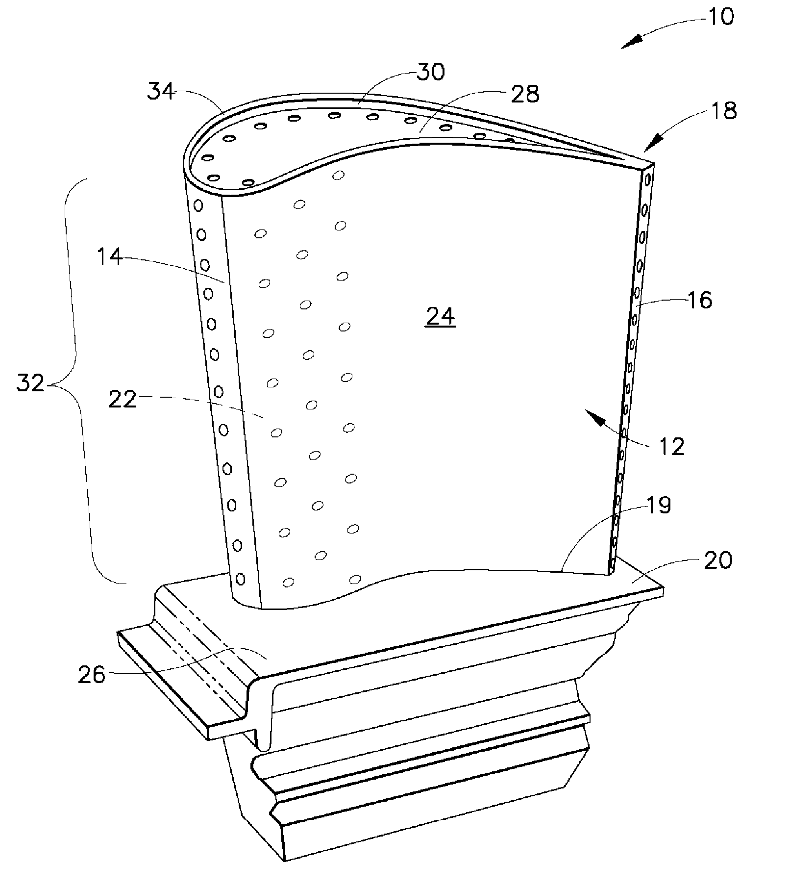
[0014] Referring to the drawings wherein identical reference numerals denote the same elements throughout the various views, FIG. 1 depicts an exemplary turbine blade 10 for a gas turbine engine. The present invention is equally applicable to the construction of other types of metallic components, such as stationary turbine vanes, frames, combustors, and the like. The turbine blade 10 comprises an airfoil 12 having a leading edge 14, a trailing edge 16, a tip 18, a platform 20, a convex suction sidewall 22, and a concave pressure sidewall 24. An arcuate inner platform 26 is attached to the platform 20 of the airfoil 12.

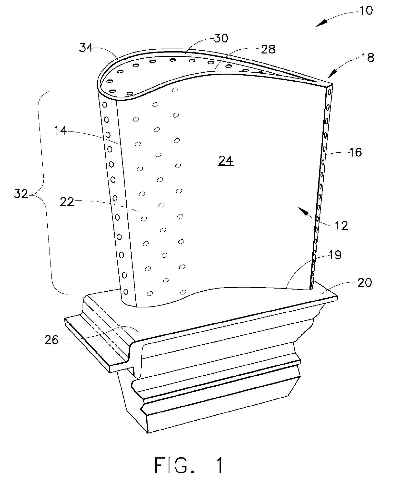
[0015] In manufacturing the airfoil 12, the pressure and suction sidewalls 24 and 22, a tip cap 28, and a partial height squealer tip 30 are integrally cast as a one-piece airfoil body 32. The airfoil body 32 is typically cast from known type of a nickel- or cobalt-based superalloy having high-temperature strength properties suitable for the intended operating condit...


PUM

PropertyMeasurementUnit
Pressureaaaaaaaaaa
Shapeaaaaaaaaaa
Metallic bondaaaaaaaaaa

Abstract

A method of producing a metallic component includes: providing a body made of a first alloy; providing a preform comprising a metallic powder made of a second alloy and formed in the shape of an extension of the body; and heating the preform with microwave energy to sinter the metallic powder together and to bond the preform to the body. The method may be used to make new components as well as to repair or modify existing components.

Description

BACKGROUND OF THE INVENTION [0001] This invention relates generally to high-temperature components for gas turbine engines and more particularly to turbine airfoils. [0002] Thermal and mechanical loads applied to the leading and trailing edges and tips of a gas turbine engine airfoil can adversely affect the airfoil's useful life. Airfoils in gas turbine engines experience durability problems at the tip of the airfoil in the form of cracking due to thermally induced stress and material loss due to oxidation and rubbing. This can be addressed by using an alloy having increased resistance to environmental oxidation and corrosion. However, it is undesirable to upgrade the entire airfoil to a more thermal-resistant and oxidation-resistant alloy because this increases component cost and perhaps weight. [0003] Materials having better high temperature properties than conventional superalloys are available. However, their increased density and cost relative to conventional superalloys disco...

Claims


Application Information

Patent Timeline
IPC IPC(8): H05B6/64
CPCB22F7/06B23P6/005B23P6/007B23P15/02B23P15/04Y10T29/49318F01D5/20F05D2230/22Y10T29/49742Y10T29/49336Y10T29/49737F01D5/005
Inventor KELLY, THOMAS JOSEPH
Owner GENERAL ELECTRIC CO
Why Eureka
Try Eureka