Relay switch including an energy detection circuit

a relay switch and energy detection technology, applied in the field of relay switches, can solve problems such as network traffic, damage, and problems such as the implementation of poe discovery using a relay as shown in fig. 1 can be problemati

Active Publication Date: 2006-12-28
MICREL
View PDF8 Cites 33 Cited by
  • Summary
  • Abstract
  • Description
  • Claims
  • Application Information

AI Technical Summary

Problems solved by technology

The discovery process ensures that devices that may not be PoE compliant are not forwarded power and thereby possibly suffer damage.
Second, a PoE compliant Powered Device may be connected to a network device that is not PoE compliant and cannot supply power.
Implementation of the PoE discovery using a relay as shown in FIG. 1 can be problematic, particularly in cases where a powered device is connected to a network device that does not support PoE.
The loop back and repeated transmission of the same data packets intended for Powered Device 2 drastically increase the network traffic and often result in jamming.
Thus, in a network configuration where a Powered Device is connected to a network device not capable of supplying power, the signal loop back discovery method can result in jamming as large amount of redundant network traffic is put back into the network by the relay.
However, the filter solution has limitations.
Thus, the filter solution does work in a 10 Base-T network because the filter cannot differentiate between the data pulses and the control pulses.
However, such technique is very difficult to implement considering the fact that the Powered Device does not have power.
While a positive wave selector can be used to accumulate power, a conventional diode rectifier cannot be used due to the voltage drop across the diode rectifier where such voltage drop is often significant compared to the magnitude of the data signals.

Method used


Image

  • Relay switch including an energy detection circuit
  • Relay switch including an energy detection circuit
  • Relay switch including an energy detection circuit

Examples


Embodiment Construction

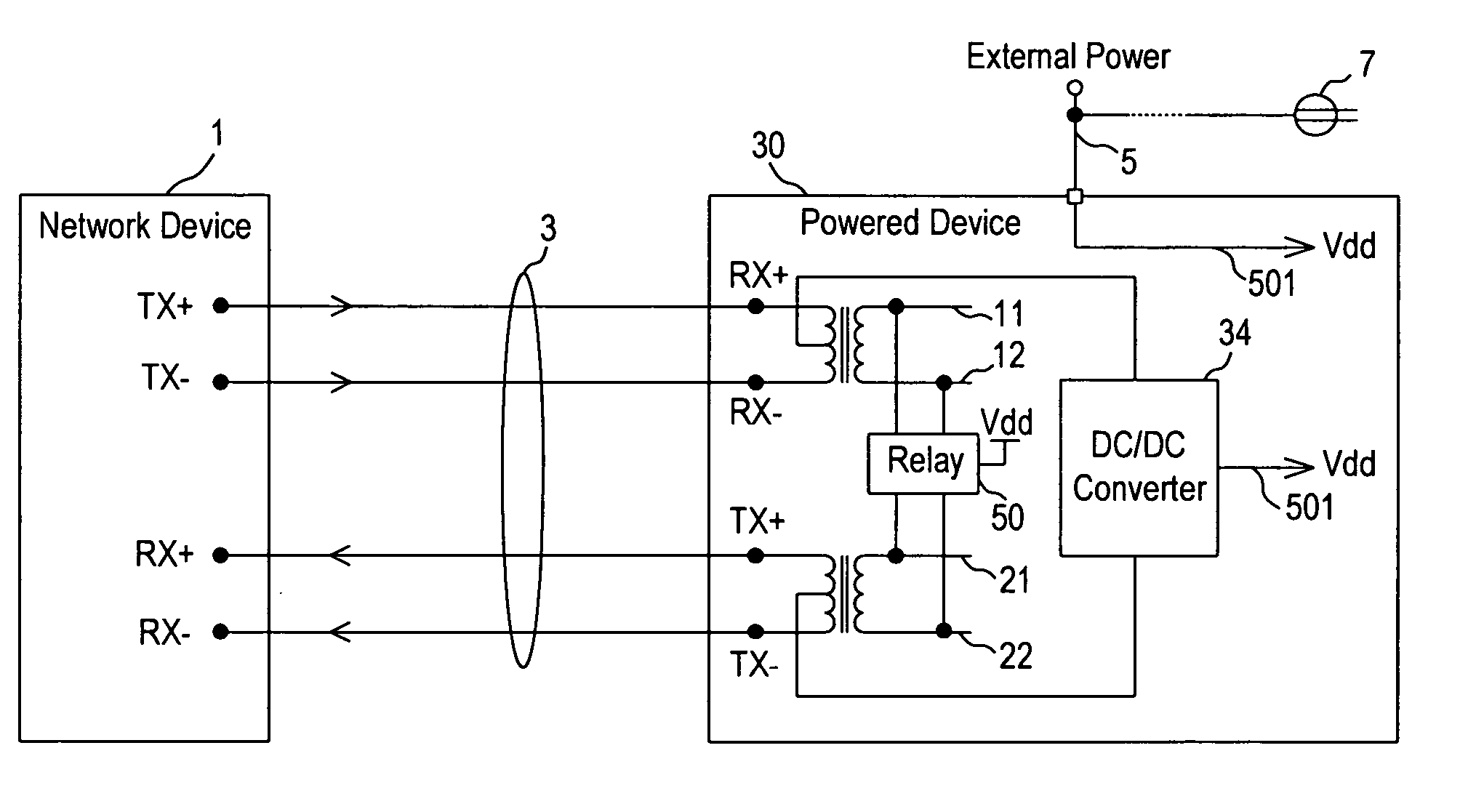
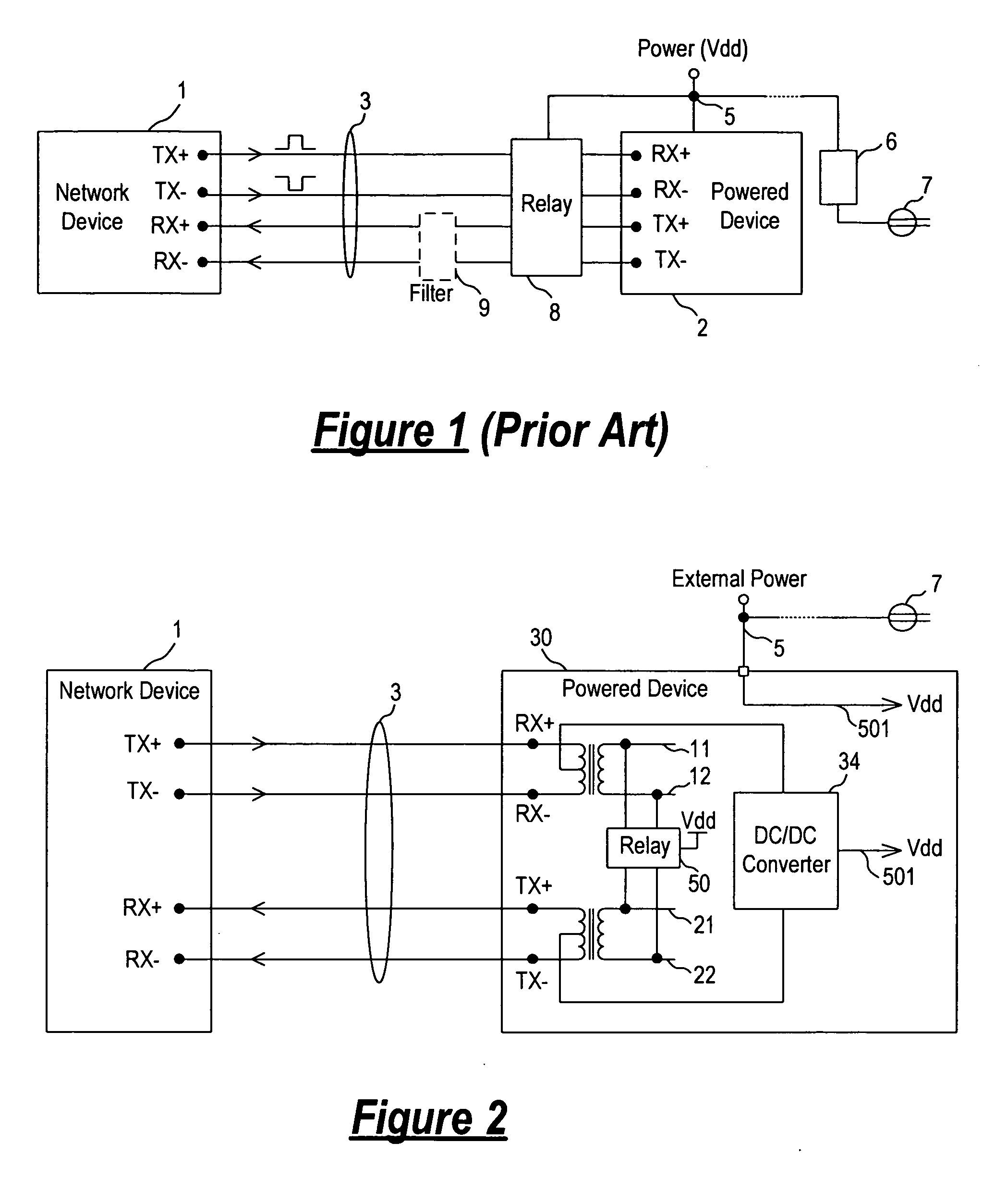
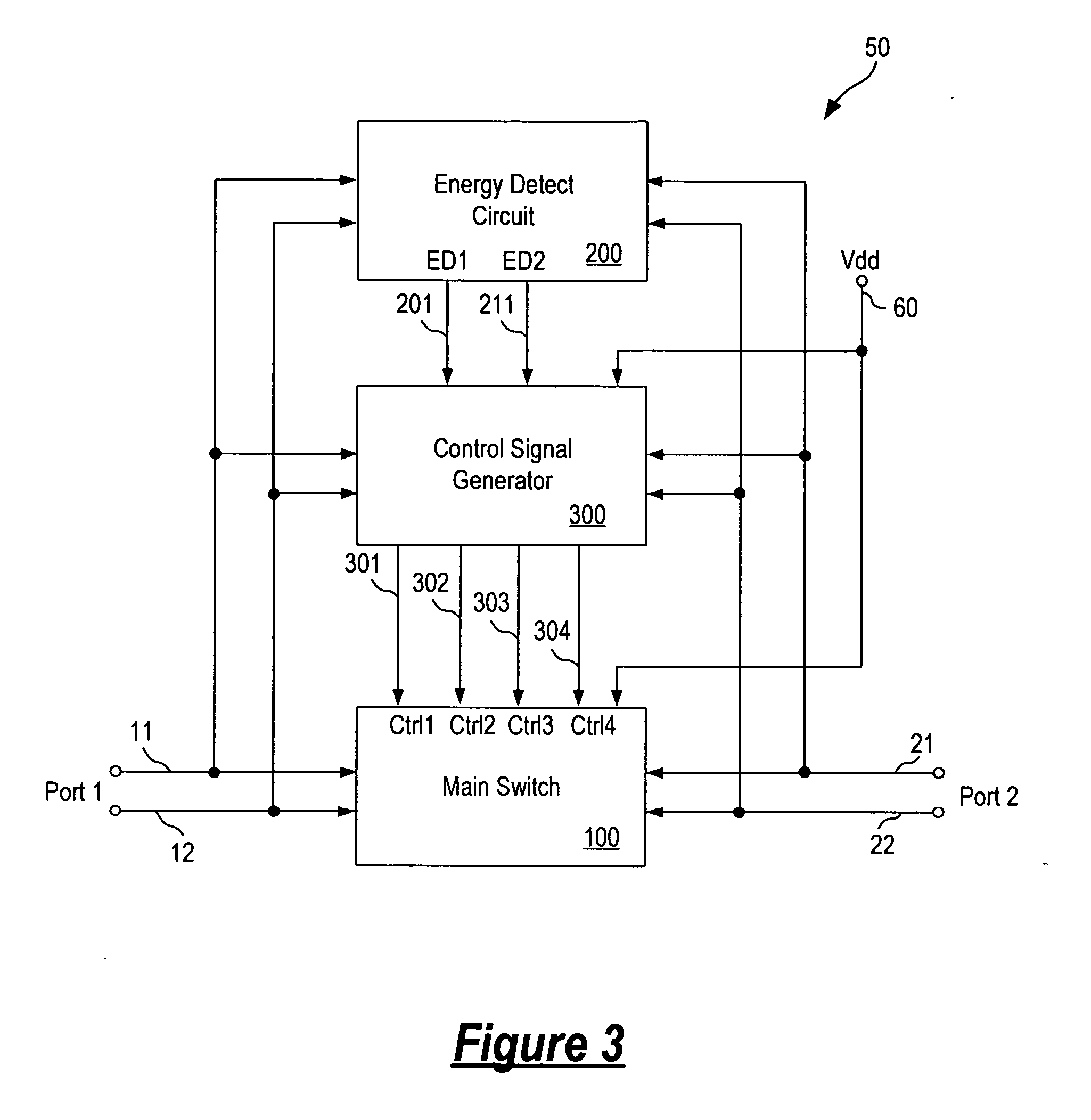
[0035] In accordance with the principles of the present invention, a semiconductor relay switch having two data ports receiving incoming signals and a power supply terminal receiving a power supply voltage is responsive to a power supply voltage level and an energy level of the incoming signals to open and close its conduction paths. The relay switch is open when a valid power supply level is detected and when there is no supply power on the power supply terminal but a high energy level is detected in the incoming signals. The relay switch is closed to allow conduction between the two data ports only when there is no power supply voltage on the power supply terminal and an energy level below a predetermined threshold is detected in the incoming signals. In one embodiment, the semiconductor relay switch includes a main conduction switch circuit, an energy detect circuit and a control signal generator.

[0036] Importantly, the relay switch of the present invention extracts energy from ...


PUM


Abstract

A semiconductor relay switch having two data ports receiving incoming signals and a power supply terminal receiving a power supply voltage is responsive to a power supply voltage level and an energy level of the incoming signals to open and close its conduction paths. The relay switch is open when a valid power supply level is detected and when there is no supply power on the power supply terminal but a high energy level is detected in the incoming signals. The relay switch is closed to allow conduction between the two data ports only when there is no power supply voltage on the power supply terminal and an energy level below a predetermined threshold is detected in the incoming signals. In one embodiment, the semiconductor relay switch includes a main conduction switch circuit, an energy detect circuit and a control signal generator.

Description

FIELD OF THE INVENTION [0001] The invention relates to relay switches and, in particular, to a relay switch that is turn on or off based in part on energy detection. DESCRIPTION OF THE RELATED ART [0002] Power Over Ethernet (PoE) technology has been developed to allow user devices, such as IP telephones, wireless LAN Access Points and other appliances, to receive power as well as data over existing network cabling, without needing to modify the existing Ethernet infrastructure. [0003] In general, a PoE network is formed by a Power Sourcing Equipment (PSE) supplying power and a Powered Device (PD) receiving and utilizing the power. A PSE, typically a midspan network device, injects power onto the twisted pair cables forming the local area network. At the other end of the cables, the power is used to run the Powered Devices so that no additional source of power needs to be provided to the Powered Devices. The Power Sourcing Equipment thereby provides on the same cable both power and d...

Claims


Application Information

Patent Timeline
Patent Type & Authority Applications(United States)
IPC IPC(8): H02B1/24
CPCH04L12/10H04L49/40Y10S307/01H01L2224/48137H01L2224/49175H01L2924/3011H01L2924/13091H01L2924/00H01L2924/00014H01L2224/45099
Inventor CHANG, MENPINGTIAN, JING
Owner MICREL
Why Eureka
Try Eureka