Measuring device for measuring differential current, trip module comprising one such measuring device and switchgear unit having one such module

a technology of differential current and measuring device, which is applied in the direction of short-circuit testing, instruments, inductances, etc., can solve the problems of tripping and protection, and achieve the effect of not being protected

Active Publication Date: 2006-12-28
SCHNEIDER ELECTRIC IND SAS
View PDF4 Cites 20 Cited by
  • Summary
  • Abstract
  • Description
  • Claims
  • Application Information

AI Technical Summary

Benefits of technology

[0013] The object of the invention is therefore to remedy the shortcomings of the state of the art so as to propose a device for measuring differential electric current having a wide measurement range enabling both weak differential currents and strong short-circuit currents to be measured.

Problems solved by technology

The shielding 10 of the differential sensor reduces the influence of the external disturbances which might in certain cases give rise to differential current measurement errors and cause spurious tripping in the event of a load surge.
In the latter architecture, protection is however not performed if a single-phase short-circuit occurs on the current line that is not provided with a current sensor.
The differential sensor generally designed to measure weak current of a few tens of milliamps is then saturated due to the presence of short-circuit current and can not provide any information.

Method used


Image

  • Measuring device for measuring differential current, trip module comprising one such measuring device and switchgear unit having one such module
  • Measuring device for measuring differential current, trip module comprising one such measuring device and switchgear unit having one such module
  • Measuring device for measuring differential current, trip module comprising one such measuring device and switchgear unit having one such module

Examples


Embodiment Construction

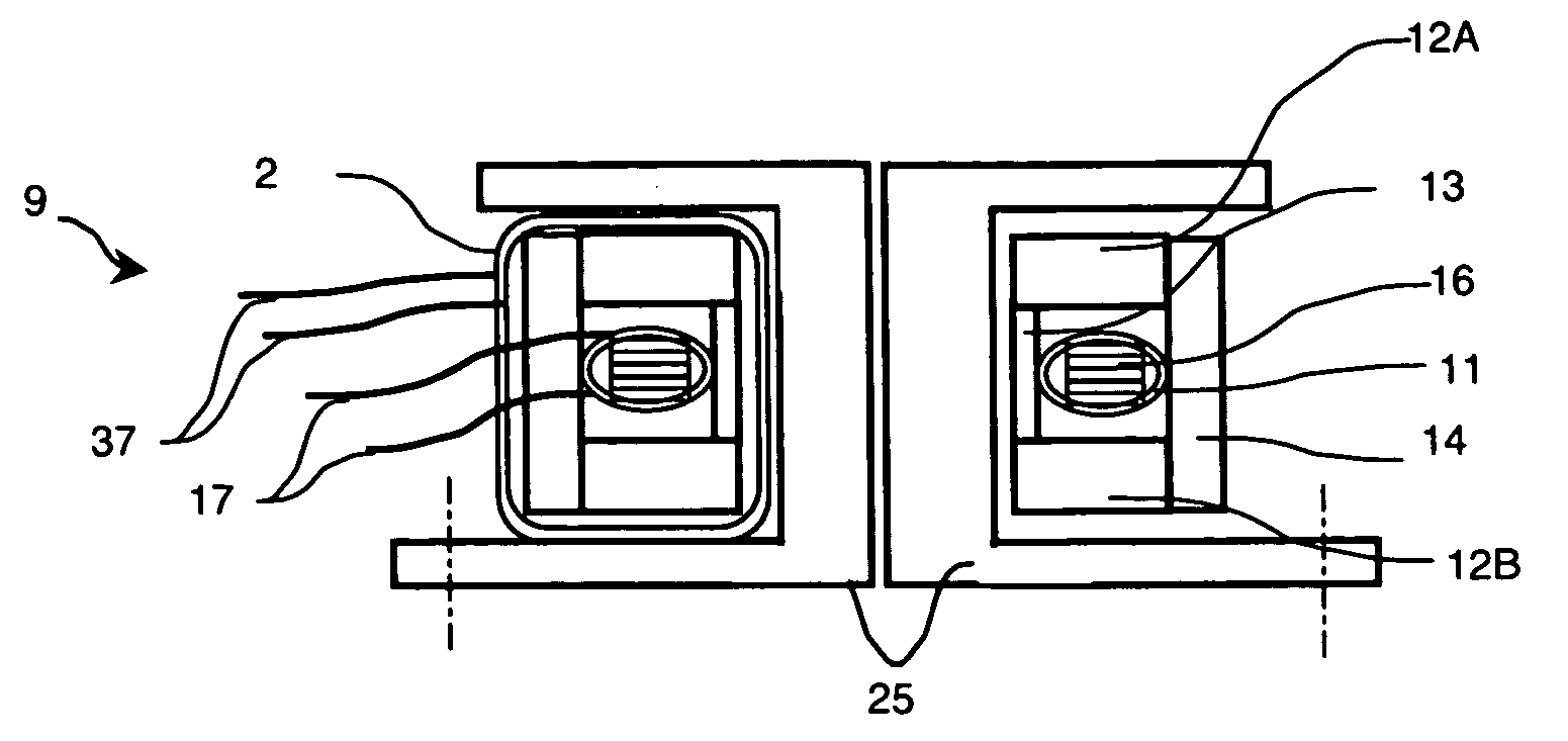
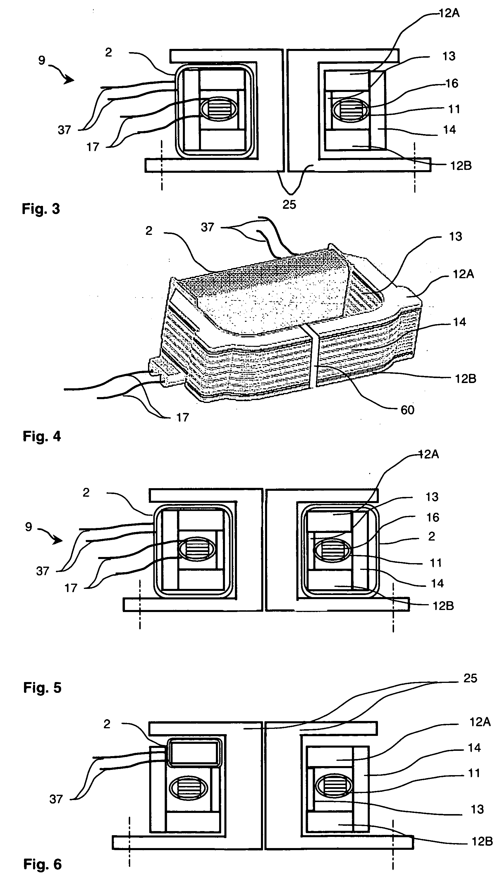
[0035] According to the preferred embodiment of the invention represented in FIGS. 3 and 4, the device for measuring differential current 9 comprises a magnetic core 16 having a substantially closed rectangular outline. Said core is made of highly permeable magnetic material from a crystalline or nanocrystalline alloy. The magnetic core 16 has a rectangular cross-section and can be made from a wound strip or from stacked plates. In order to optimize the sensitivity of the device for measuring differential current 9, the core 16 does not have an air-gap. Said core is designed to be fitted surrounding current lines 25.

[0036] The magnetic core 16 is surrounded by a first secondary winding 11 designed to measure a differential current able to flow in the current lines 25. The first secondary winding 11 is arranged over the whole perimeter of the magnetic core 16.

[0037] This first secondary winding 11 thus forms the secondary winding of a current transformer. The primary circuit is for...


PUM

PropertyMeasurementUnit
currentsaaaaaaaaaa
differential currentaaaaaaaaaa
shapeaaaaaaaaaa

Abstract

A device for measuring differential current designed to measure differential current in at least two current lines, comprising a first magnetic circuit designed to surround the current lines, forming a primary circuit of a transformer, a first secondary winding wound around said magnetic circuit and forming the secondary circuit of the transformer, a metal shielding surrounding the first secondary winding and the magnetic circuit. The device for measuring differential current in addition comprises at least one second secondary winding surrounding at least a part of the metal shielding. This second winding forms a second magnetic circuit of at least one second current sensor designed to supply an electric signal representative of a current flowing in at least one current line.

Description

BACKGROUND OF THE INVENTION [0001] The invention relates to a device for measuring differential current in at least two current lines. Said device comprises a first magnetic circuit designed to surround the current lines, forming a primary circuit of a transformer and comprises a first secondary winding wound around said magnetic circuit and forming the secondary circuit of the transformer. A metal shielding surrounds the first secondary winding and the magnetic circuit. STATE OF THE ART [0002] To detect the presence of differential currents flowing in electric current lines or electric conductors 25, it is extremely common practice to use differential sensors comprising a first secondary winding 11 wound around a magnetic core 16. As represented in FIGS. 1 and 2, said core, in particular circular or rectangular in shape, surrounds the electric current lines or the electric conductors 25. The electric current lines or the electric conductors will henceforth be called current lines. ...

Claims


Application Information

Patent Timeline
Patent Type & Authority Applications(United States)
IPC IPC(8): H01F27/36G01R15/18G01R19/00
CPCG01R1/18G01R15/183H01H83/226H01F27/365H01F38/30G01R31/025G01R31/52H01F27/36H01F27/366H02H1/0007H02H3/33H02H3/347
Inventor MAS, PATRICKBUFFAT, SEBASTIEN
Owner SCHNEIDER ELECTRIC IND SAS
Why Eureka
Try Eureka