Display panel conversion data deciding method and measuring apparatus

a technology of conversion data and display panel, which is applied in the direction of identification means, instruments, static indicating devices, etc., can solve the problems of large fluctuations in the luminance of each pixel, inability to disregarded the changes over time in the light emission properties of a light-emitting element itself, and insufficient driving current obtained. to achieve the effect of correcting the variations in the luminance of the display panel

Inactive Publication Date: 2006-12-28
AGILENT TECH INC
View PDF23 Cites 145 Cited by
  • Summary
  • Abstract
  • Description
  • Claims
  • Application Information

AI Technical Summary

Benefits of technology

[0009] That is, even if there is a pixel present in the display panel in which the capacitor has not been sufficiently discharged prior to the test, it is possible to cancel the driving current of that pixel and perform high-speed measurement of variations in properties between pixels by using a method whereby the driving current of light-emitting elements of a display panel are measured before a pixel under test is measured and the driving current of the light-emitting elements of the pixel under test is found based on the difference from the driving current of the light-emitting elements of the display panel when the pixel under test has been driven. Furthermore, measurement at an even higher speed is possible by measuring, before the light-emitting elements are driven, every predetermined number of pixels and interpolating from the measurement results the current before driving unmeasured pixels. In this case, there are fluctuations in the properties of each pixel and the precise pre-driving current therefore cannot be found by interpolation, but because the absolute fluctuations are small in proportion to the amount of discharge, the effect of the variations between adjacent pixels can be disregarded.
[0010] Moreover, the present invention solves the above-mentioned problems with a method for determining the conversion data of a display panel, characterized in that it is a method for determining the conversion data of a display panel having a display panel comprising a TFT array and self-emitting elements, a luminance signal generating means for generating luminance signals by converting luminance data to conversion data, a drive means for driving the self-emitting elements by the luminance signals, and a measurement means for measuring the driving current and / or emission luminance of the light-emitting elements of the TFT array, and in comprising a step for driving the self-emitting element of the pixel under test, a step for performing the measurement before the driving current of the pixel under test has reached a saturated state, and a step for determining the conversion data based on the results of the measurement. That is, measurement at an even higher speed is possible by performing the measurement before the emission luminance or driving current of the pixel under test reaches a saturated state (the emission luminance or measurement current reach the steady state when an element is driven).
[0011] The present invention makes possible the high-speed correction of variations in luminance of a display panel.

Problems solved by technology

When the amorphous silicon film that has been used for years in liquid crystal display panels is employed in TFT arrays for display panels with self-emitting elements, it is often the case that an insufficient driving current is obtained because the carrier mobility is low.
That is, there are large fluctuations in the luminance of each pixel during production of TFT arrays that use low-temperature polysilicon film.
In addition, changes over time in the light emission properties of a light-emitting element itself cannot be disregarded.
Such fluctuations in emission luminance are a source of display panel defects manifested as image irregularities and color changes.
Consequently, there is a problem with continuous measurement of the many pixels in a display panel in that such measurement takes a very long time.

Method used


Image

  • Display panel conversion data deciding method and measuring apparatus
  • Display panel conversion data deciding method and measuring apparatus
  • Display panel conversion data deciding method and measuring apparatus

Examples


Embodiment Construction

[0020] Preferred embodiments of the display device of the present invention will now be described in detail while referring to the attached drawing. EL elements are used as the self-emitting elements in these examples, but the present invention is not limited to an EL display panel and can be used on display panels that use other self-emitting elements, such as a display panel that uses light-emitting diodes.

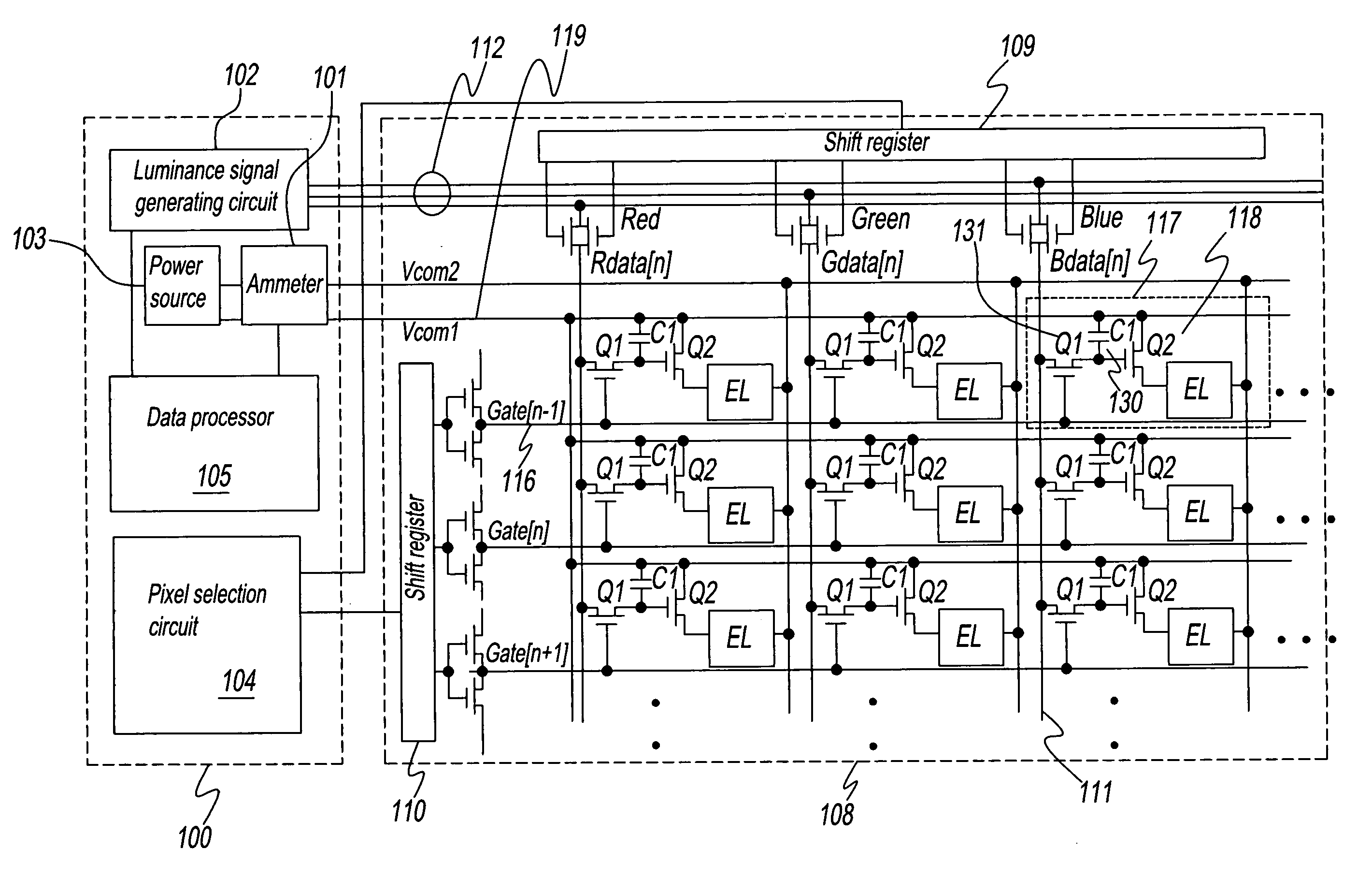
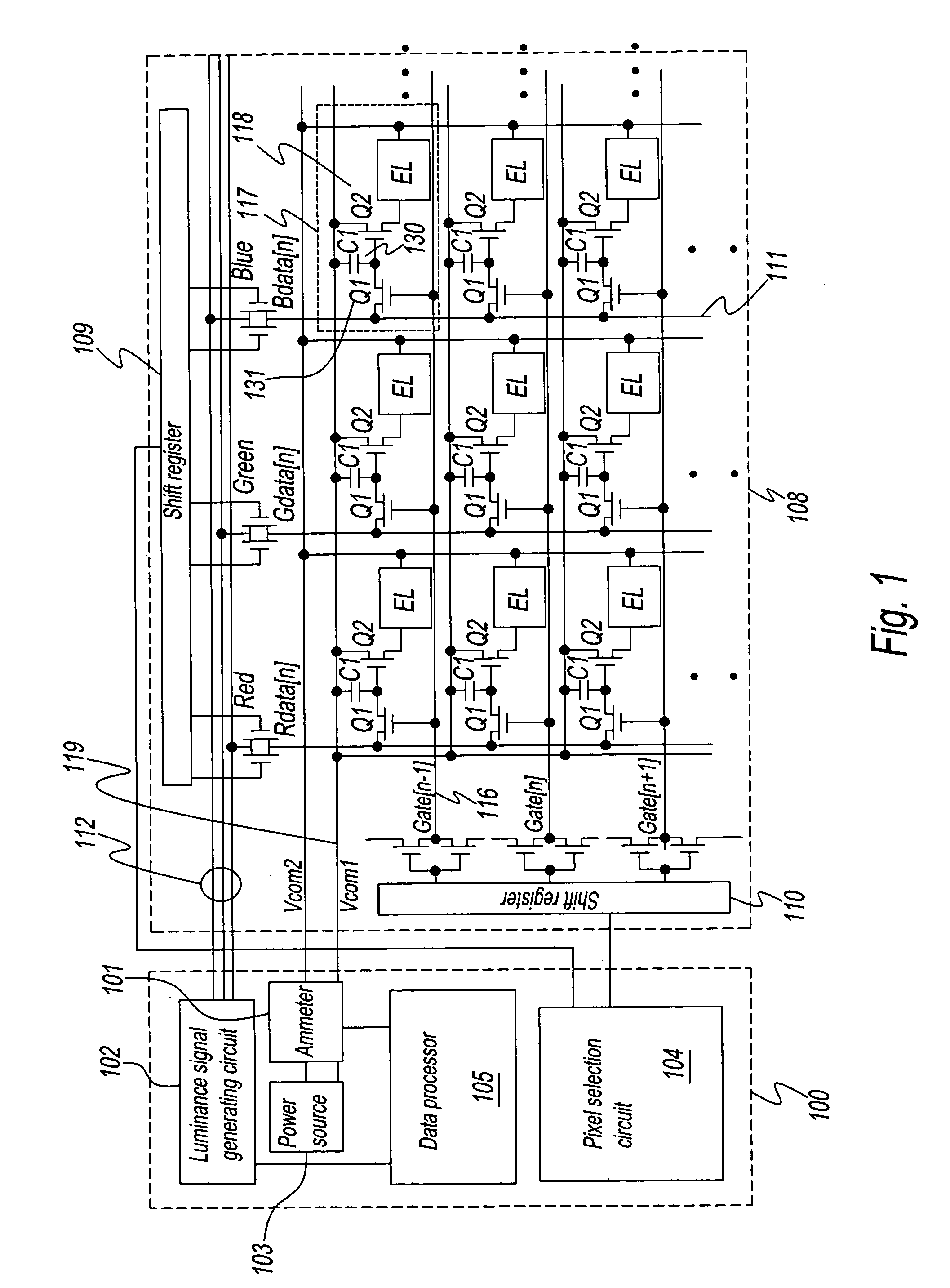
[0021]FIG. 1 is a structural diagram of the display device of the present invention. The display device comprises a control part 100 of the panel and an EL display panel 108. Control part 100 comprises: a selection means in the form of a pixel selection circuit 104 connected to shift registers 109 and 110 of EL display panel 108; a luminance signal generating circuit 102, which is connected to the outside input of luminance data and a luminance signal line 112 of EL display panel 108, and provides the conversion data of each pixel; a measurement means in the form of an ammeter ...


PUM


Abstract

A high-speed correction of display panel luminance variation is performed by use of a display panel conversion data deciding method, which comprises a first measuring step for determining a first driving current of the light emitting elements of the display panel when the capacitors of the pixels other than pixels to be measured have not completely been discharged; a charging step for charging, by an analog voltage, the capacitors of the pixels to be measured; a second measuring step for determining a first driving current of the light emitting elements of the display panel when the capacitors of the pixels to be measured have been charged by the analog voltage; a driving current calculating step for determining, from the difference between the first and second driving currents, the driving current of the pixels to be measured; and a data calculating step for determining conversion data based on the driving current.

Description

1. FIELD OF THE INVENTION [0001] The present invention relates to a method for determining the conversion data of a display panel, particularly a method for determining the luminance conversion data for correcting variations in luminance of a TFT array display panel having self-emitting elements, and a display device that uses this method. 2. DISCUSSION OF THE BACKGROUND ART [0002] Flat display panels used in flat-screen televisions, monitors of personal computers, display devices of portable telephones, and the like must be capable of responding to fast-moving images and of vivid color reproduction. In light of such demands, attention has recently been focused on thin film transistor (TFT) arrays with a fast response speed and active display panels that use organic EL elements and other self-emitting elements with a wide range of display colors. [0003] Self-emitting elements are emission elements that generate light in accordance with the amount of current flowing to the element. A...

Claims


Application Information

Patent Timeline
Patent Type & Authority Applications(United States)
IPC IPC(8): G09G3/30G09F9/00G09G3/20H01L51/50H05B33/14
CPCG09G3/30G09G2320/029G09G2320/02G09G2300/0809G09G3/20
Inventor GOTO, MASAHARU
Owner AGILENT TECH INC
Why Eureka
Try Eureka