Optical recording medium, and information recording/playback apparatus and method using the medium

a recording medium and information technology, applied in the field of recordable and/or erasable information recording mediums, can solve problems such as easy errors, deterioration of information on a certain track, and deterioration of the shape of the mark

Inactive Publication Date: 2006-12-28
KK TOSHIBA
View PDF13 Cites 10 Cited by
  • Summary
  • Abstract
  • Description
  • Claims
  • Application Information

AI Technical Summary

Benefits of technology

[0089] The effect of the interface film of the invention is significant when the recording film is made of a GeSbTe-based material, and the composition of the recording film used in practicing the invention contains a so-called pseudo-binary composition represented by (GeTe)−(Sb2Te3) and its vicinity. The effect is particularly remarkable when the interface film of the invention is used for an alloy recording film material containing the composition (GeTe)−(Sb2Te3) described above and its vicinity in which the composition ratio of Ge is 30 at. % or more.
[0090] The effect is more noticeable when the interface film is used as a composition obtained by partially substituting Ge with Sn or partially substituting Sb with Bi and / or In in the composition GeSbTe described above. In this case, the substitution ratio of Sn to Ge is preferably Sn / Ge<0.5, and that of Bi to Sb is preferably Bi / (Bi+Sb)<0.7.
[0091] Here, 0.5 or less is suitable for the rate of In to the quantity of Sb or Bi, and 0.25 or less is more suitable. The quantity of the substitution element closely relates to crystallization temperature, melting temperature, and / or crystallization promotion function. Although the optimal conditions may change with designs of a medium, it is recommendable to use the rate within the above range (i.e., less than or equal to 0.5 or 0.25).
[0092] The effect of the interface film of the invention is significant when the recording film is made of GeBiTe, and a so-called pseudo-binary composition represented by (GeTe)—(Bi2Te3) and its vicinity are used. The effect is particularly significant when the interface film of the invention is used for an alloy recording film material containing the composition (GeTe)—(Bi2Te3) described above and its vicinity in which the composition ratio of Ge is 30 at. % or more.
[0093] When the recording film contains nitrogen (N), the composition is represented by (GeTe)—(Sb2Te3)—N, i.e., the composition is obtained by adding nitrogen (N) to (GeTe)—(Sb2Te3). That is, the composition is obtained by adding nitrogen (N) to a pseudo-binary series represented by (GeTe)—(Sb2Te3). This composition can be more simply represented by GeSbTe—N. The effect of the interface film of the invention is remarkable when it is used together with this recording film. The effect is particularly notable when the interface film of the invention is used for an alloy recording film material containing the composition (GeTe)—(Sb2Te3) described above and its vicinity in which the composition ratio of Ge is 30 at. % or more.
[0094] The effect is further enhanced when the interface film is used for a composition obtained by partially substituting Ge with Sn or partially substituting Sb with Bi and / or In in the composition GeSbTe—N described above. In this case, the substitution ratio of Sn to Ge is preferably Sn / Ge<0.5, and that of Bi to Sb is preferably Bi / (Bi+Sb)<0.7.

Problems solved by technology

However, if the recording marks are close to each other, a signal having a small amplitude is obtained, so an error easily occurs when the signal is converted into digital data.
Unfortunately, this method has the problem that in a region where the track pitch is equal to or smaller than the size of a light beam, information on a certain track deteriorates while write or erase is performed on an adjacent track.
The causes of the cross erase are that a mark is directly irradiated with the outer edge of a laser beam on an adjacent track, and that a hot stream during recording flows into an adjacent track and raises the temperature of a mark on the adjacent track, thereby deteriorating the shape of the mark.
To ensure the erase ratio described above, however, improvements of the recording film material are unsatisfactory, and a film having a crystallization promoting effect is formed in the interface with the recording film.
However, the inventors made extensive studies, and found that when a very thin film made of the recording film material described above and having a thickness of 10 nm or less is combined with the conventional interface film material such as GeN, the cross erase described previously occurred, so the track pitch could not be decreased.
Also, when silicon carbide (SiC) reportedly having a crystallization promoting function is used, the extinction coefficient of light is large at a wavelength of 405 nm of a laser beam used for the next-generation, high-density optical disc, and this produced a very large optical loss.
In addition, germanium nitride (GeN) or silicon nitride (SiNx) also produced an optical loss.
On the other hand, in a medium having no interface film, it is possible to suppress recrystallization of the melted portion and reduce the cross erase, but the erase ratio is totally unsatisfactory.
One main cause which prevents high-speed recording in phase change recording is the problem that information is kept unerased when crystallization is performed by a laser having a relatively low erase level during overwrite, i.e., the problem of an insufficient erase ratio.
This problem arises because a recording mark rapidly passes through a laser spot and hence does not stay in a temperature region capable of crystallization for a sufficiently long time, so information is kept unerased.
The use of an interface film like this melts an unwanted large region, and consequently accelerates the cross erase.
Accordingly, this method has an adverse effect from the viewpoint of high-density recording.
On the other hand, in a medium having no interface film, it is possible to suppress recrystallization of the melted portion and reduce the cross erase, but the erase ratio is totally unsatisfactory.
However, it is impossible to systematically measure the thermo-physical properties of a thin film on the nanometer order while removing the effects of other factors, although several researches suggested that they are different from bulk thermo-physical properties.
In particular, there is almost no method of measuring the boundary thermal resistance between thin films on the nanometer order.
Since the optical loss increases, this material cannot be used in the next-generation, high-density medium.
GeN described previously is not also transparent at wavelength λ=405 nm, and increases the optical loss.
As described above, none of the presently known techniques can provide an interface layer material which is optically transparent at a wavelength of 405 nm or less and has the crystallization promoting function.
In addition, when the eutectic series is used, it is very difficult to perform so-called land-groove recording by which information is recorded on and played back from both a land (L) and groove (G), since the melt erase mode is used as described above.
This makes the eutectic series very disadvantageous in increasing the recording density.

Method used


Image

  • Optical recording medium, and information recording/playback apparatus and method using the medium
  • Optical recording medium, and information recording/playback apparatus and method using the medium
  • Optical recording medium, and information recording/playback apparatus and method using the medium

Examples


first embodiment

[First Embodiment]

[0111] Prior to a description of an embodiment of an optical recording medium manufactured by way of trial, the extinction coefficient of a thin film made of Zr (zirconium), O (oxygen), N (nitrogen), and one or both of Y (yttrium) and Nb (niobium) according to this embodiment will be explained in detail below. Several samples are manufactured by changing the composition ratio of the composition represented by (ZrO2−xNx)1−y((Y2O3)1−z(Nb2O5)z)y of a thin film made of Zr, O, N, and one or both of Y and Nb of this embodiment within the ranges of 0

[0112] More specifically, samples having compositions shown in FIG. 3 are manufactured and evaluated. FIG. 3 shows data obtained near a wavelength of 405 nm as the wavelength used by this optical recording medium. As indic...

third embodiment

[Third Embodiment]

[0140] Discs having the same arrangement as that of the second embodiment are formed by using, as interface layers, compositions which are made of Zr (zirconium), O (oxygen), N (nitrogen), and one or both of Y (yttrium) and Nb (niobium) (represented by (Zro2−xNx)1−y((Y2O3)1−z(Nb2O5)z)y, and had composition ratios shown in FIG. 4, and the same experiments as in the second embodiment are conducted. FIG. 9 shows the results. As shown in FIG. 9, the SbER of each sample is on the order of 10−5 for both lands and grooves, i.e., a practical error rate is obtained by each sample. The CNR for analog data is also as high as 52 dB or more for both lands and grooves. The OW count of each medium is 2,000 or more, i.e., a practical characteristic is obtained. In addition, no peeling is found in the film after the environmental test.

[0141] The criteria of total evaluation in the third embodiment shown in FIG. 9 are that the CNR is 52 dB or more, the SbER is 2×10⁻⁵ or less, the w...

fourth embodiment

[Fourth Embodiment]

[0142] As substrates, 0.59-mm thick polycarbonate (PC) substrates formed by injection molding are used. Since grooves are formed at a groove pitch of 0.68 μm, the track pitch is 0.34 μm when data is recorded on both lands (L) and grooves (G). In information layer L0 formed by using a sputtering apparatus close to the light incident side on the surface of this PC substrate in which the grooves are formed, ZnS:SiO2, an interface layer, a recording film layer, an interface layer, an Ag alloy, and an interface layer material are sequentially formed. In information layer L1 formed far from the light incident side, an Ag alloy, an interface layer, a recording film layer, an interface layer, and ZnS:SiO2 are sequentially stacked in this order from the PC substrate.

[0143] The same material as in the second embodiment is used as the recording film, and the film thickness of the recording film is 10 nm or less. A disc is formed by using, as an interface layer, a compositio...


PUM

PropertyMeasurementUnit
transmittanceaaaaaaaaaa
thicknessaaaaaaaaaa
total thicknessaaaaaaaaaa

Abstract

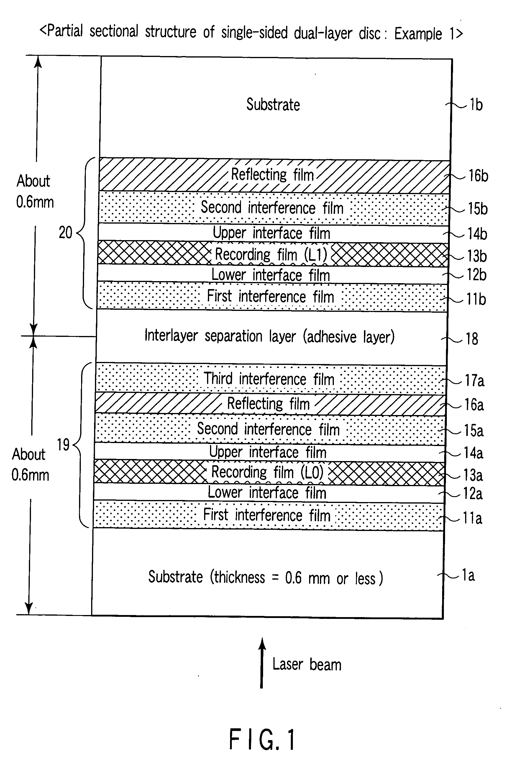
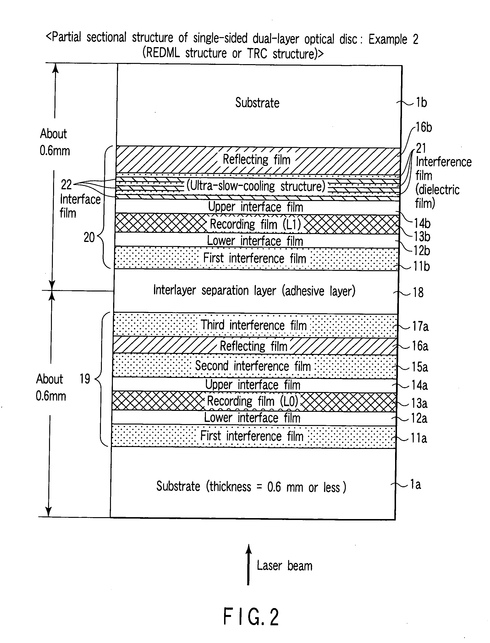
In a single-sided, recordable/rewritable phase change optical recording medium having one or more layers, an interface layer adjacent to a phase change optical recording film contains at least Zr (zirconium), O (oxygen), and N (nitrogen), and further contains one or both of Y (yttrium) and Nb (niobium).

Description

CROSS-REFERENCE TO RELATED APPLICATIONS [0001] This application is based upon and claims the benefit of priority from Japanese Patent Application No. 2005-168344, filed Jun. 8, 2005, the entire contents of which are incorporated herein by reference. BACKGROUND [0002] 1. Field [0003] One embodiment of the invention relates to a recordable and / or erasable information recording medium. This embodiment particularly relates to an optical recording medium having one or more recording films configured to record information by using a phase change. More specifically, the embodiment relates to a single-sided, multi-layer phase change optical disc suitable for repetitive recording / playback of large-volume digital data such as high-resolution video information. [0004] Or, one embodiment of the invention relates to an optical recording medium which records information by reversibly changing a state by emitting a light beam. This embodiment particularly relates to a phase change optical recordin...

Claims


Application Information

Patent Timeline
Patent Type & Authority Applications(United States)
IPC IPC(8): G11B3/70G11B7/24G11B7/243G11B7/2433G11B7/2437G11B7/257
CPCG11B7/24038G11B7/243G11B7/256G11B2007/24322G11B2007/24312G11B2007/24314G11B2007/24316G11B7/257
Inventor NAKAI, TSUKASAOOMACHI, NORITAKEASHIDA, SUMIONAKAMURA, NAOMASAYUSU, KEIICHIROSATOH, YASUHIRO
Owner KK TOSHIBA
Why Eureka
Try Eureka