
Novel pilot sequences and structures with low peak-to-average power ratio

Inactive Publication Date: 2006-12-28
NOKIA CORP
View PDF10 Cites 78 Cited by
  • Summary
  • Abstract
  • Description
  • Claims
  • Application Information

AI Technical Summary

Benefits of technology

[0012] It is therefore an object of the invention to provide a method for generating a pilot signal sequence for a data transmission from a transmitter to a receiver via a transmission carrier that allows reducing the peak-to-average transmission power ratio.
[0013] It is a further object of the invention to provide a method for generating a part at signal sequence for a data transmission from a transmitter to a receiver via a transmission carrier that allows increasing the area coverage of the transmitter.
[0014] It is a further object of the invention to provide a method for generating a pilot signal sequence for a data transmission from a transmitter to a receiver via a transmission carrier that reduces the cost of providing radio transmission capacity.

Problems solved by technology

As is well known, the transmission properties of wireless transmission channels vary in time due to various time-dependent effects such as noise and interference.
However, this approach is tedious, especially in a system providing several bandwidth options such as the coming 3.9G system.
However, the 3.9G system requires a particularly low peak-to-average ratio (PAR).
Since upper transmission power limits prescribed by national technical regulations or technical limitations must be adhered to, a high PAR bears the disadvantage of having to provide power resources, which are not used during a large fraction of a transmission (forming the average value), but only during short peak instances.
A system based on a rather small area coverage is expensive because it requires the installation of a larger number of base station transceivers.

Method used


Image

  • Novel pilot sequences and structures with low peak-to-average power ratio
  • Novel pilot sequences and structures with low peak-to-average power ratio
  • Novel pilot sequences and structures with low peak-to-average power ratio

Examples


Embodiment Construction

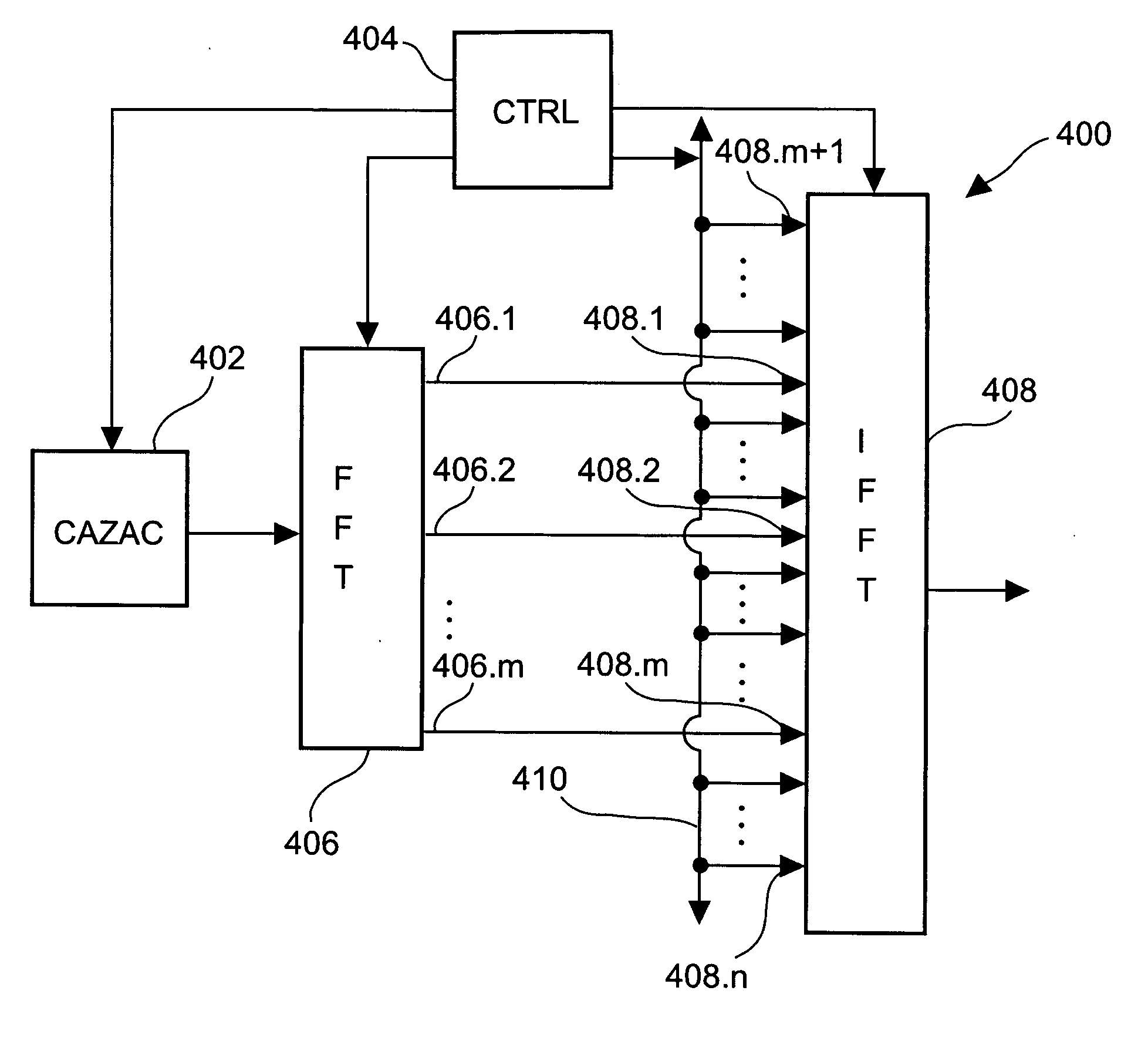
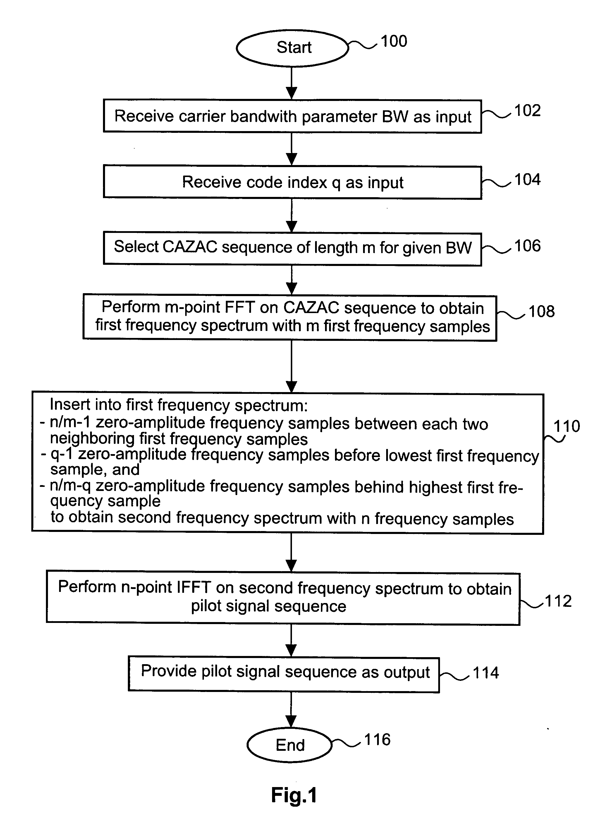
[0132]FIG. 1 shows a flow diagram of a method for generating a pilot signal sequence according to an embodiment of the invention. The procedure is started with step 100. At step 102, a carrier bandwidth parameter BW is received as an input. The carrier bandwidth influences the selection of a CAZAC sequence performed in step 106. At step 104 a code index is received as a further input value. At step 106, a CAZAC sequence of length m is selected from a stored set of CAZAC frequencies. The length m of the CAZAC frequency is the number of sequence elements. A sequence element of a CAZAC sequence is a symbol representing a complex number such as 1, −1, j, and −j. An example of a CAZAC sequence of length 16 is given in US 2005 / 0084030 A1 as:

[0133] 1,1,1,1,1,i,1,−i,−1,1,−i,−1,i.

[0134] Here, i refers to the well known imaginary unit number i, which in US 2005 / 0084030 A1 is denoted as “j”. In step 108, an n-point Fast Fourier transform is performed on the CAZAC sequence. A first frequency ...


PUM


Abstract

Pilot signal sequences with a low Peak-to-average ratio are generated by a method comprising the steps of providing a first signal sequence consisting of a first number, m, of signal elements and known to have a frequency spectrum with either identical or nearly identical non-zero amplitude values in a first frequency interval, performing an invertible first transformation of the first signal sequence into a first frequency spectrum in the first frequency interval, the first frequency spectrum consisting of m first frequency samples, performing a second transformation of the first frequency spectrum into a second frequency spectrum consisting of n frequency samples in the first frequency interval, the n frequency samples being formed by the m first frequency samples and a third number, n minus m, of additional second frequency samples, which have zero amplitude, such that the second frequency spectrum has m frequency spikes distributed over the second frequency interval, and performing a third transformation, which forms an inverse of the first transformation, to the second frequency spectrum to obtain a second signal sequence forming the pilot signal sequence.]

Description

FIELD OF THE INVENTION [0001] The invention relates to a method for generating a pilot signal sequence for a data transmission from a transmitter to a receiver via a transmission carrier. It further relates to a pilot signal sequence, a method for transmitting data from a transmitter to a receiver using a Frequency Division Multiple Access (FDMA) technique via a transmission carrier, device for generating a pilot signal sequence for a data transmission from a transmitter to a receiver via a transmission carrier a transmitter, and a receiver. BACKGROUND OF THE INVENTION [0002] Pilot signal sequences find widespread use in telecommunication technologies. A pilot signal sequence is a signal sequence, which is transmitted via a transmission channel for purposes of control, equalization, synchronization, or similar purposes. [0003] As is well known, the transmission properties of wireless transmission channels vary in time due to various time-dependent effects such as noise and interfere...

Claims


Application Information

Patent Timeline
IPC IPC(8): H04B7/216
CPCH04L27/262H04L27/2613H04L27/26134
Inventor PAJUKOSKI, KARITIIROLA, ESA
Owner NOKIA CORP
Learn More