Fuel channel characterization method and device

a fuel assembly and characterization method technology, applied in the field of non-destructive testing systems of fuel assemblies, can solve the problems of fuel assembly installation problems, fuel assembly channel degradation of boiler water reactors, damage to the underlying structure of fuel assemblies, etc., and achieve the effect of economic accuracy and fast manner

Inactive Publication Date: 2006-12-28
DAVIS MICHAEL D +3
View PDF20 Cites 11 Cited by
  • Summary
  • Abstract
  • Description
  • Claims
  • Application Information

AI Technical Summary

Benefits of technology

[0013] It is a still further objective of the present invention to provide a system to identify defects in nuclear fuel assembly fuel channels in an economical accurate and fast manner.

Problems solved by technology

Industry experience has indicated that boiling water reactor fuel assembly channels undergo significant degradation when exposed to flux gradients in the nuclear reactor core.
This deformation can lead to fuel assembly installation problems in the confines of a nuclear reactor.
Additionally, when the fuel channel is removed from the exterior of a nuclear fuel assembly, the dechanneling operation may result in a stuck fuel channel, or the fuel channel may damage the underlying structure of the fuel assembly.
An additional problem that may be encountered for fuel channels which have been deformed is the interaction of the fuel assembly with control rod blades which traverse the reactor.
There are currently no methods or apparatus to measure fuel assembly overall dimensions to ensure compliance of the fuel assembly to expected design parameters.
Other performance issues have also been identified with relation to nuclear fuel assembly fuel channels, e.g., hydride-induced channel bow arising from shadow-corrosion effects on control.

Method used


Image

  • Fuel channel characterization method and device
  • Fuel channel characterization method and device
  • Fuel channel characterization method and device

Examples


Embodiment Construction

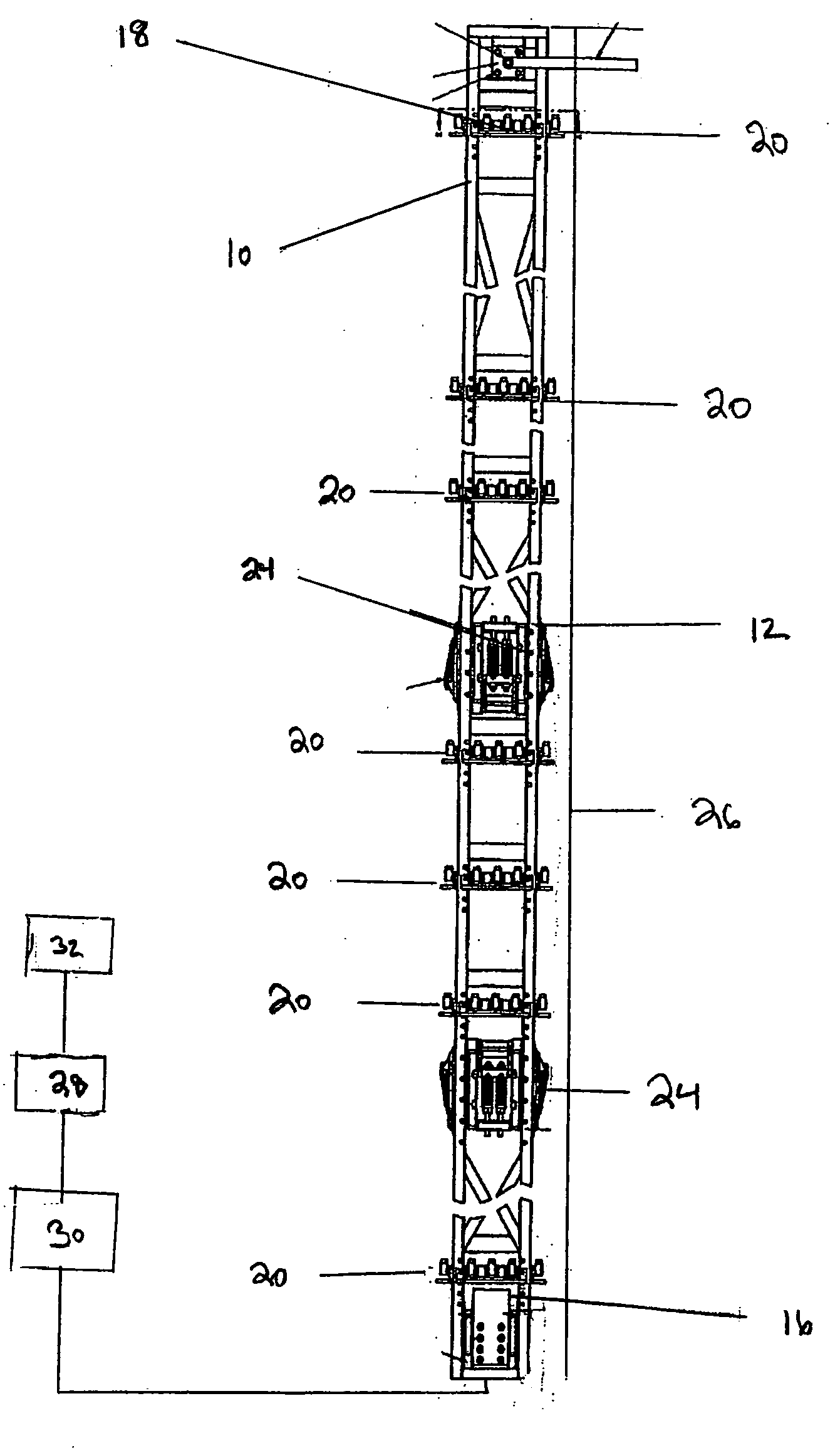
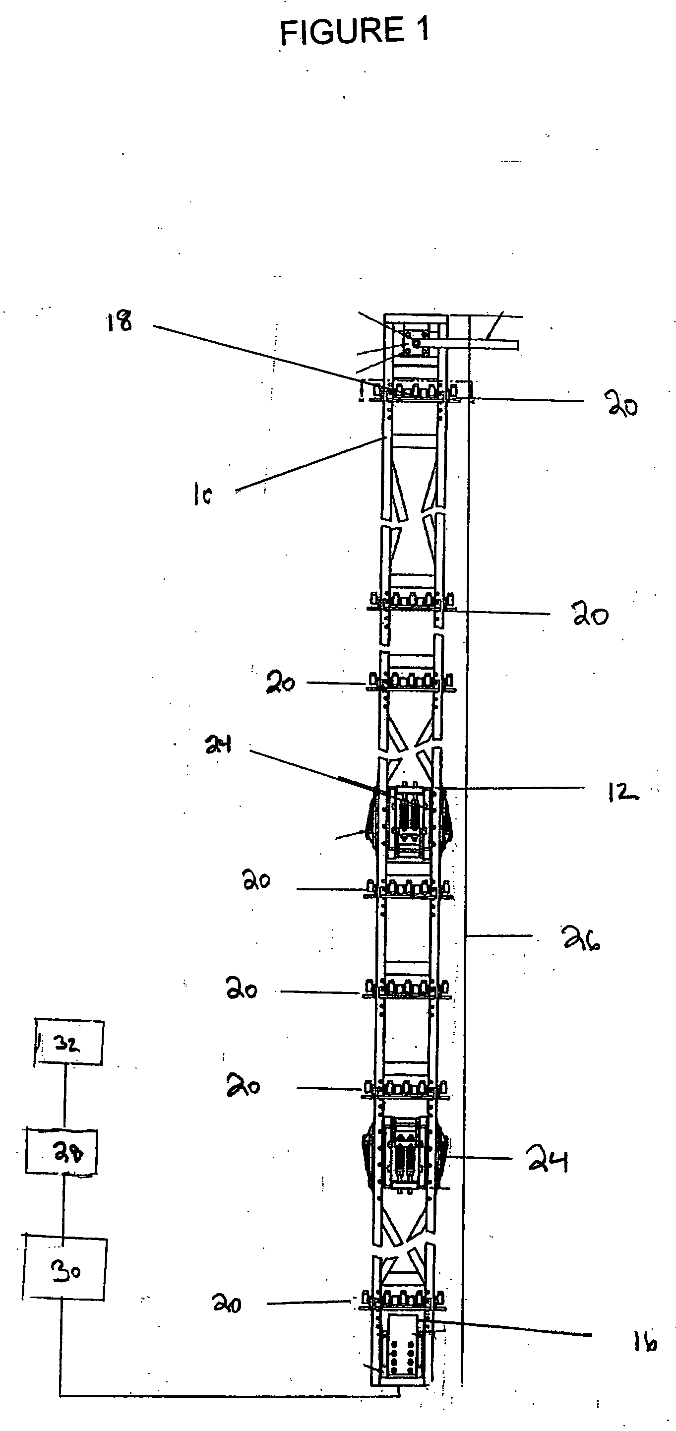
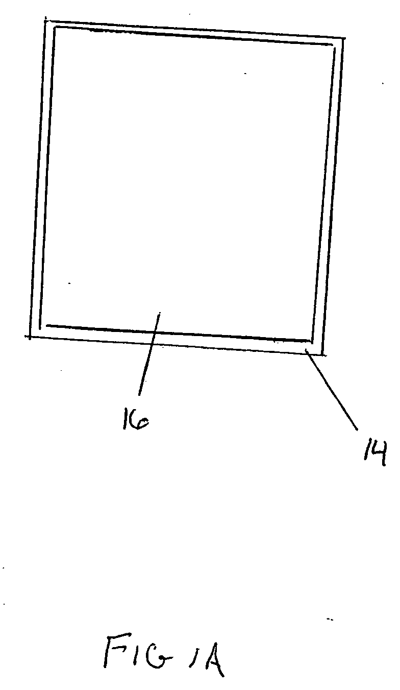
[0025] Referring to FIGS. 1 and 1A, a boiling water reactor channel measurement system 10 in conformance with the present invention is illustrated. The measurement system 10 of the present invention is comprised of a rigid support frame 12 which is used to support a series of special immersion ultrasonic transducers 20. The rigid support frame 12 is designed to allow simultaneous distance measurements of a boiling water reactor fuel channel 14, thereby allowing for precise dimensional profiling of the fuel channel 14. The rigid frame 12 is designed to interface with support structures commonly found in nuclear power plant facilities, thereby allowing placement of the rigid frame 12 in a variety of placement areas such as storage pools or reactor cavities. These support structures include fuel handling cranes and / or manipulator cranes commonly used in nuclear reactor core and spent fuel pool locations. The boiling water reactor fuel channel 14, complete with fuel assembly 16 or decha...


PUM


Abstract

An apparatus to measure external dimensions of a fuel channel of a boiling water reactor, having a rigid frame which has a lower seat to accept a nozzle of a nuclear fuel assembly, the rigid frame extending an entire length of the nuclear fuel assembly, an inspection arrangement including ultrasonic transducers placed upon the rigid frame, the ultrasonic transducers supported by the rigid frame, the ultrasonic transducers configured to generate and receive ultrasonic signals imparted into a medium and generate an electrical signal upon receipt of the ultrasonic signal, a signal processing arrangement configured to evaluate electrical signals received from the inspection arrangement, and a series of leads connected to the arrangement of ultrasonic transducers, the series of leads taking the electrical signals generated by the inspection arrangement of ultrasonic transducers and transporting the electrical signals from the ultrasonic transducers to the signal processing arrangement.

Description

RELATED APPLICATIONS [0001] Pursuant to 35 U.S.C. § 120, the present application claims the benefit of U.S. Ser. No. 11 / 058,058, filed Feb. 14, 2005.FIELD OF INVENTION [0002] The present invention relates to the field of measuring fuel assemblies through an ultrasonic measurement system. More specifically, the present invention relates to a system for non-destructive testing of a fuel assembly in order to measure the physical characteristics and dimensional behavior of irradiated boiling water reactor fuel channels using a time-domain analysis of ultrasound pulses imparted to the fuel channel to be measured. BACKGROUND INFORMATION [0003] Non-destructive testing relates to the field of using non-invasive techniques to obtain information about the integrity or physical characteristics of structures. Examples of this technology include ultrasonic flaw detection in fuel cladding for nuclear fuel assemblies. Ultrasonic acoustic measurement is but one such system used for non-destructive ...

Claims


Application Information

Patent Timeline
Patent Type & Authority Applications(United States)
IPC IPC(8): G21C17/00
CPCG01N29/07G01N29/11G01N2291/02854G01N2291/044G01N2291/2634G21Y2004/40G21Y2002/201G21Y2002/204G21Y2002/304G21Y2004/30G21C17/06Y02E30/30
Inventor DAVIS, MICHAEL D.CLARK, DAREL R.VAN BERGEN, JOHN W.PUGH, ANTHONY
Owner DAVIS MICHAEL D
Why Eureka
Try Eureka