System and method for Hilbert phase imaging

Active Publication Date: 2006-12-28
MASSACHUSETTS INST OF TECH +1
View PDF11 Cites 40 Cited by
  • Summary
  • Abstract
  • Description
  • Claims
  • Application Information

AI Technical Summary

Benefits of technology

[0002] Many processes that take place at the cellular level, including cytoskeletal dynamics, cell membrane fluctuations and neural activity occur at shorter time scales, down t

Problems solved by technology

In HPM, single-shot phase imaging is limited in frame acquisiti

Method used


Image

  • System and method for Hilbert phase imaging
  • System and method for Hilbert phase imaging
  • System and method for Hilbert phase imaging

Examples


Embodiment Construction

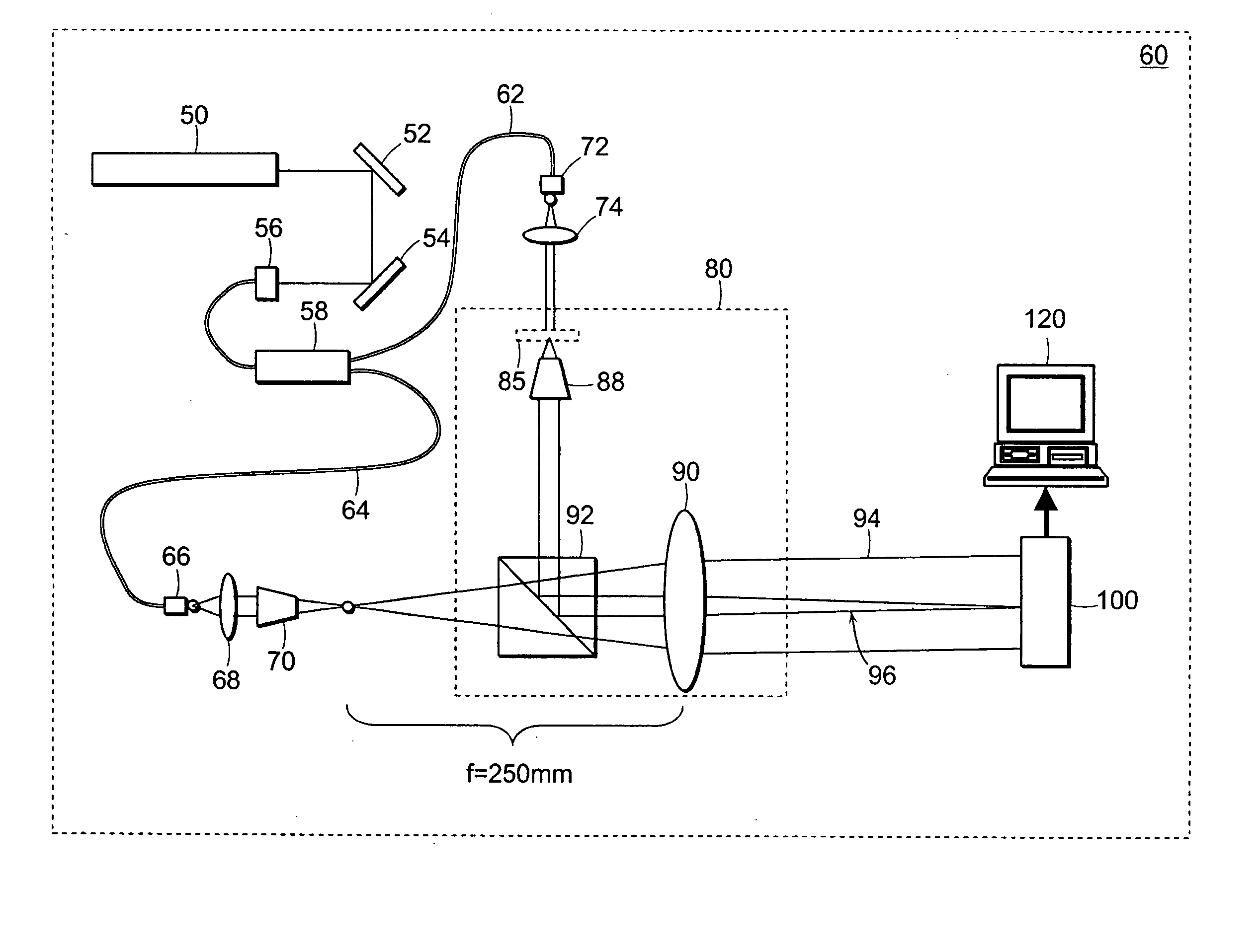
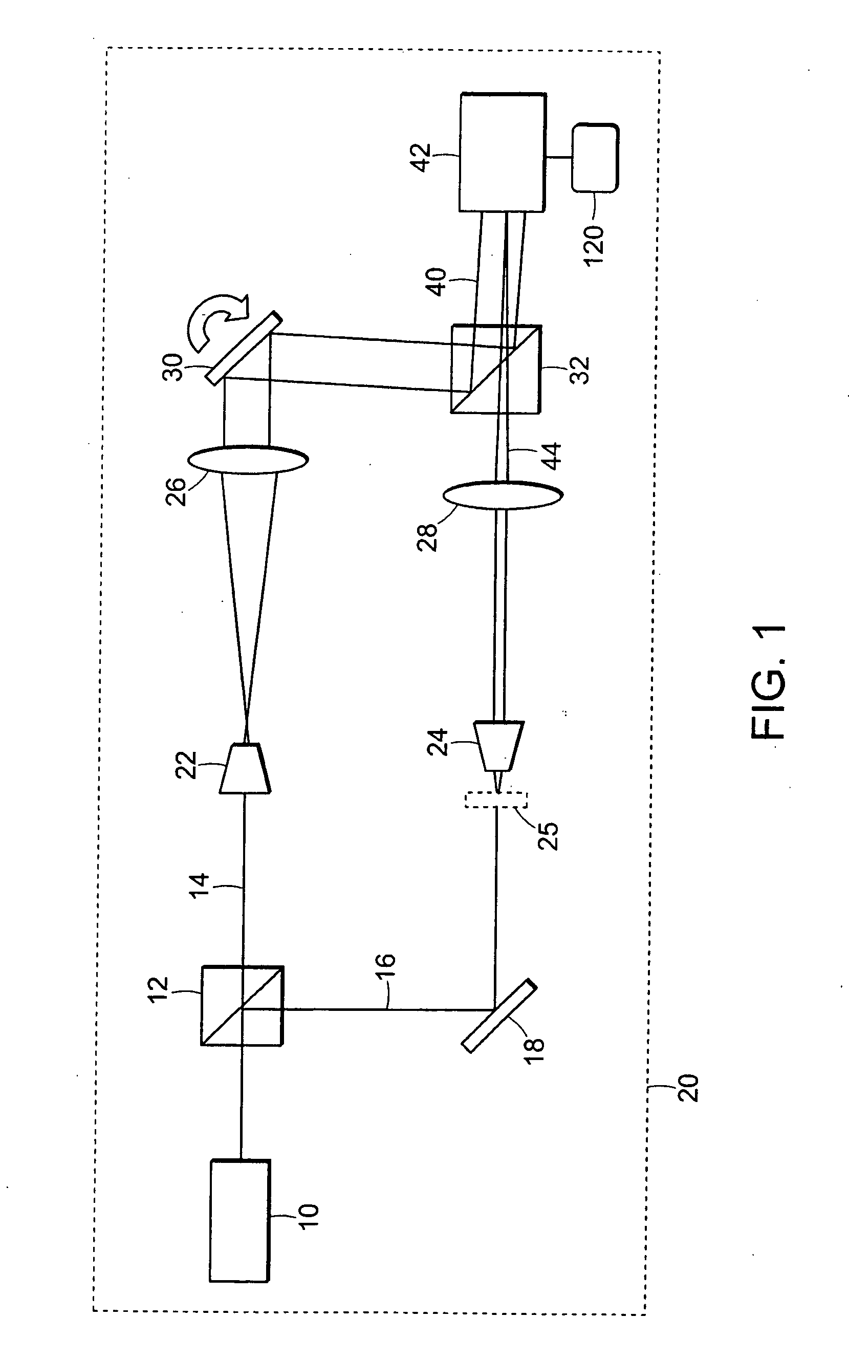
[0016] A preferred embodiment of the invention is illustrated in FIG. 1. In this embodiment a HeNe laser is used as a light source 10 for an imaging Mach-Zender interferometer 20. A first beam splitter 12 splits the beam from the light source 10 to form two arms of the interferometer, the arms comprising a reference beam 14 and a sample beam 16, respectively. A mirror 18 directs the sample beam 16 onto a sample or object 25. In each arm of the interferometer 20 there are two telescopic systems, with magnification M=20 for example, each telescopic system comprises an objective 22, 24 and a lens 26, 28. A second mirror 30 directs the reference field onto a second beam splitter 32. The orientation of the reference field 40 is adjustable, for example, by rotatable movement of mirror 30 in order to tilt reference field 40. An image sensor 42, such as a CCD, can be positioned in the common Fourier plane of the lenses 26, 28 where the exact (magnified) replica of the sample field 44 is for...


PUM


Abstract

Hilbert phase microscopy (HPM) as an optical technique for measuring high transverse resolution quantitative phase images associated with optically transparent objects. Due to its single-shot nature, HPM is suitable for investigating rapid phenomena that take place in transparent structures such as biological cells. A preferred embodiment is used for measuring biological systems including measurements on red blood cells, while its ability to quantify dynamic processes on the millisecond scale, for example, can be illustrated with measurements on evaporating micron-size water droplets.

Description

BACKGROUND OF THE INVENTION [0001] Optical microscopy has been a commonly used method of investigation in medicine and biology. Numerous biological samples, including live cells, are quite transparent under visible light illumination and behave essentially as phase objects. Techniques such as phase contrast and Nomarski microscopy provide contrast of nearly invisible samples by transforming the phase information into intensity distribution and thus reveal structural details of biological systems. However, the information obtained with these techniques about the phase shift associated with the illuminating field is only qualitative. Retrieving quantitative phase information from transparent objects with high accuracy and low noise allows for measurements in the biological investigation of structure and dynamics. Both interferometric and non-interferometric techniques have been proposed for quantitative phase imaging of biological samples. Also Fourier phase microscopy (FPM) has been ...

Claims


Application Information

Patent Timeline
IPC IPC(8): G06K9/00
CPCG01N15/1475G01N21/453G01N2015/0073G01N2015/008G01N2015/145H01L27/14601G01N2015/1497G06K9/00134G01N15/10G01N33/49G01N2015/1454G06V20/693
Inventor POPESCU, GABRIELDASARI, RAMACHANDRAFELD, MICHAELIKEDA, TAKAHIRO
Owner MASSACHUSETTS INST OF TECH
Why Eureka
Try Eureka