Method for measuring concentration of polyelectrolyte and phosphonate blends

a technology which is applied in the field of determining the concentration of polyelectrolyte and phosphonate blends, can solve the problems of difficult or even impossible quantification, and achieve the effect of reducing the difficulty of quantification

Pending Publication Date: 2021-12-16
KEMIRA OY
View PDF0 Cites 1 Cited by
  • Summary
  • Abstract
  • Description
  • Claims
  • Application Information

AI Technical Summary

Benefits of technology

[0012]It was also surprisingly found that the different signals of the polyelectrolyte and phosphonate could be standardized to the same level by acidification of the sample. Suitable acidification treatments change the TRF signal of the different polymers into the same level, enabling quantification of polyelectrolyte and phosphonate blends independent on the fractions of the polymers present in the sample.
[0013]By combining the total measurement of the present invention with suitable separation methods of the analytes or measurement methods specific for single polyelectrolyte or phosphonate in blend, the polyelectrolyte and phosphonate blend compositions can be completely solved.

Problems solved by technology

If the fractions of the polymers in the blend change in use, reliable quantification has been challenging or even impossible, because the polymers give different TRF signals.

Method used


Image

  • Method for measuring concentration of polyelectrolyte and phosphonate blends

Examples


example 1

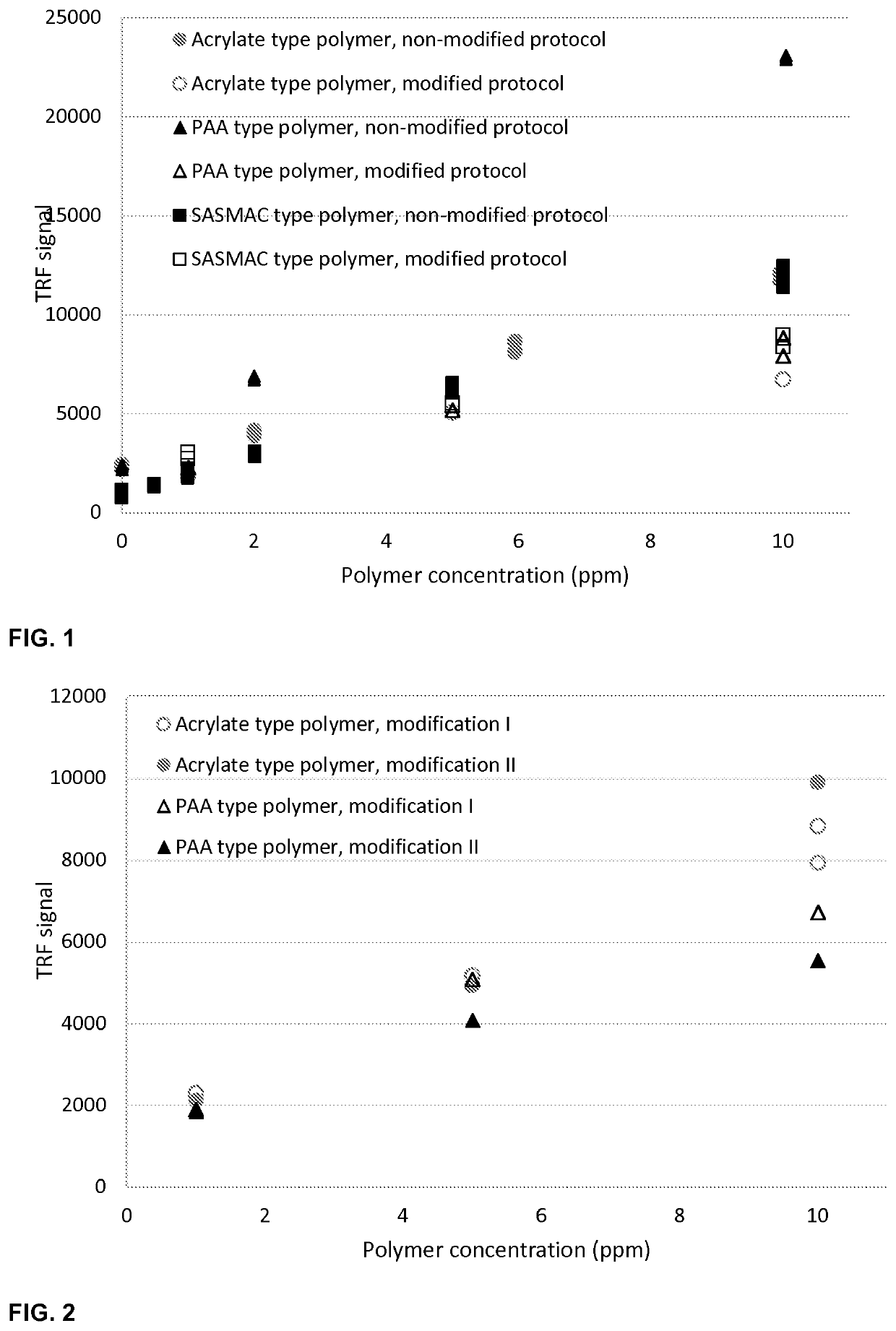
zation (Modification) of the TRF Signal of Polyacrylic Acids, Polyacrylates, SASMAC and AA-AMPS Copolymers or a Polymer Blend Thereof (According to the Invention)

[0057]The polymer or polymer blend is optionally diluted to suitable concentration range. Preferably, the active concentration of the sample and europium lanthanide are 0.5-50 ppm and μM, respectively. Optionally the polymer is diluted to suitable aqueous solution e.g. deionized water or brine containing monovalent and / or divalent ions. Preferably, the dissolution brine does not contain any trivalent ions. If the polymer solution contains some interfering compounds, suitable pretreatment procedures may be applied prior to the dilution steps. In the example, the polymers were diluted into a brine, which TDS varied between 20 000 and 40 000 ppm. The brines contain alkaline and earth alkaline metals as chlorides or bicarbonates.

[0058]After the optional dilution of the polymer, the solution is acidified to suitable pH range. Pr...

example 2

xture of Polyacrylic Acid and Fluorescence Tagged SASMAC (According to the Invention)

[0061]The binary mixture composition of polyacrylic acid and fluorescence tagged SASMAC can be examined by first using the modification method presented in Example 1. In the modification, the high signal of polyacrylic acid is reduced into the same level as that of SASMAC.

[0062]After total measurement, tagged SASMAC polymer can be measured with fluorescence method specific for the tag. For instance, sodium styrene sulfonate (NaSS) tagged SASMAC polymer can be quantified by fluorescence measurement of the product. Tag specific excitation and emission wavelengths are used in the measurement. In the case of NaSS tag, excitation and emission wavelengths of 225 nm and 285 nm can be used. The calibration standards of NaSS tagged SASMAC are measured similarly as the product and the fluorescence signal are converted into concentration of the polymer.

[0063]Polyacrylic acid concentration is obtained by subtra...


PUM

PropertyMeasurementUnit
delay timeaaaaaaaaaa
emission wavelengthaaaaaaaaaa

Abstract

The present invention relates to utilization of lanthanide time resolved fluorescence for determining total concentration of polyelectrolyte or phosphonate in a sample. In the method sample comprising two or more polyelectrolytes and/or phosphonates is acidified followed by admixing the acidified sample with a reagent comprising a lanthanide(lll) ion. The polyelectrolyte or phosphonate in the sample are allowed to interact with the reagent comprising the lanthanide(lll) ion, followed by exciting the sample and detecting a signal deriving from the lanthanide(lll) ion, and determining the concentration of the polyelectrolyte or phosphonate in the sample by using the detected signal.

Description

FIELD OF INVENTION[0001]The present invention relates to a method for determining concentration of polyelectrolyte and phosphonate blends in a sample with time-resolved fluorescence.BACKGROUND[0002]Quantification of polyelectrolytes such as organic polymers is essential in many fields of industry, such as in water treatment, paper and oil industries. The organic polymers desired to be analyzed may be corrosion inhibitors, antiscalants or enhanced oil recovery (EOR) polymers.[0003]Organic polymers can be measured in a rapid and easy manner by utilizing time-resolved fluorescence (TRF) of lanthanides(III). Europium(III) and terbium(III) are the most used lanthanide ions in TRF measurements, but also other lanthanides can be used. Organic polymers containing two or more chelating groups often increase the inherently weak TRF intensity of lanthanide(III) ions.[0004]The chelating groups of the polymer may be e.g. carboxylates, sulfonates, carboxamides, phosphates, phosphonates or amines....

Claims


Application Information

Patent Timeline
Patent Type & Authority Applications(United States)
IPC IPC(8): G01N21/77G01N21/64G01N1/28G01N31/22
CPCG01N21/77G01N21/6408G01N21/6428G01N2021/7786G01N31/22G01N2021/6439G01N1/28G01N33/582
Inventor PUUPPONEN, SALLAKRAPU, SARI
Owner KEMIRA OY
Why Eureka
Try Eureka