Profile correction for RFID label with transponder

Inactive Publication Date: 2006-12-28
INTERMEC IP
View PDF19 Cites 10 Cited by
  • Summary
  • Abstract
  • Description
  • Claims
  • Application Information

AI Technical Summary

Benefits of technology

[0014] A fourth preferred embodiment uses a low viscosity of adhesive on the label substrate that allows the transponder to compress into the adh

Problems solved by technology

This results in a more pronounced up transition a

Method used


Image

  • Profile correction for RFID label with transponder
  • Profile correction for RFID label with transponder
  • Profile correction for RFID label with transponder

Examples


Embodiment Construction

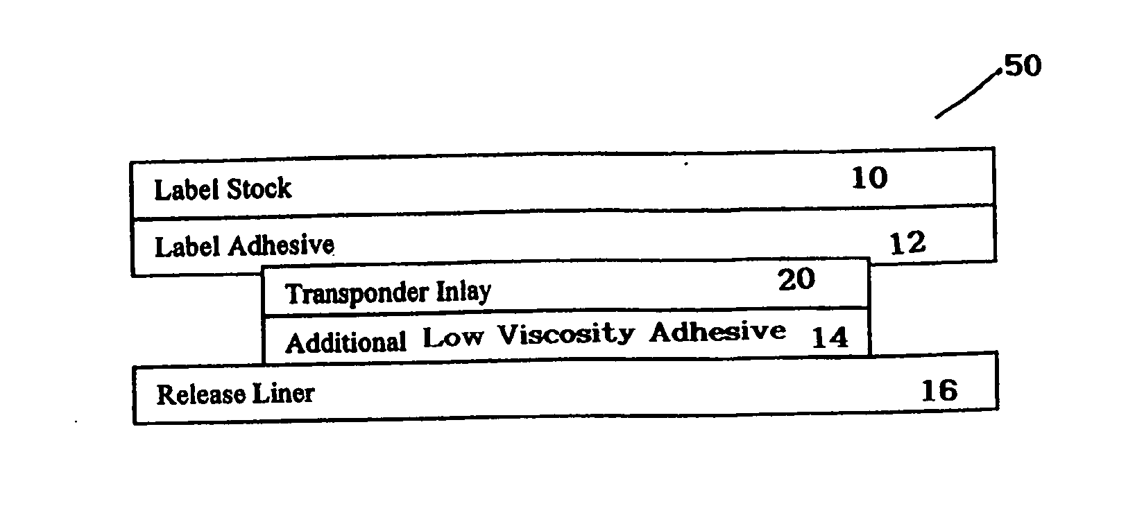
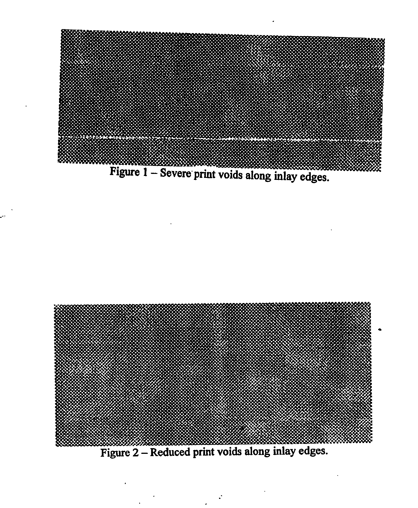
[0023] The inventive smart label construction provides a more uniform profile for improved print performance in a thermal label printer as shown in FIG. 2. Label 50 comprises label face stock 10, an adhesive layer 12 on adhesive face stock, an RFID insert 20 (also known as a chip, tag, transponder). Label 50 may be on release liner 16. The label construction has a layer of pressure sensitive adhesive 14 of applied over the inlay 20 and beyond the edges of the inlay 20. Extending adhesive layer 14 beyond inlay edges 20 provides a smoother step transition, which eliminates printing voids along inlay 20 edges.

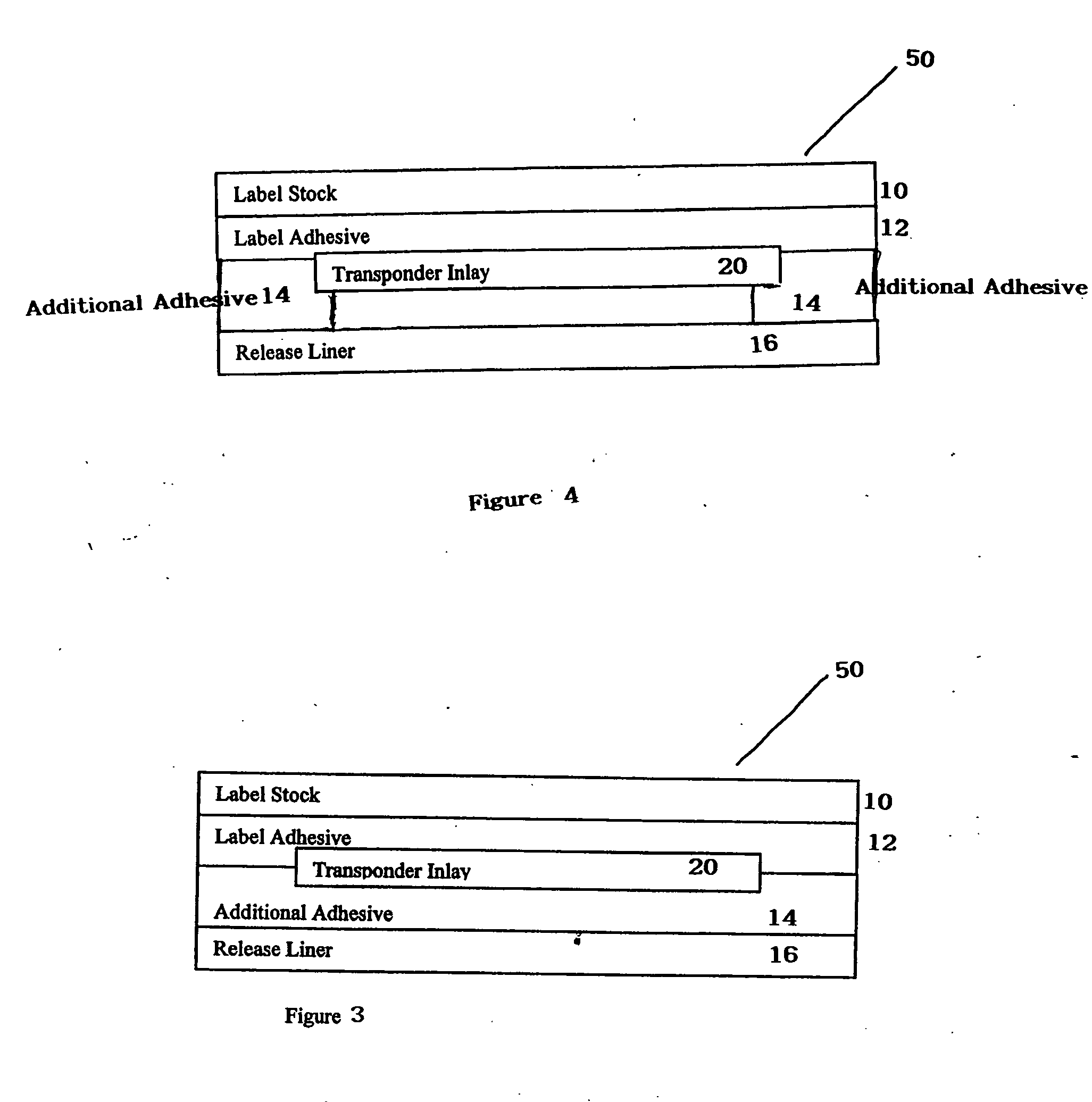
[0024] A first preferred method of applying additional adhesive layer 14 is to have additional adhesive layer 14 extend out beyond the perimeter edges of inlay 20, thus masking the thickness transition of the inlay 20 and base film 10 as shown in FIG. 3. This can be accomplished by applying an oversized adhesive patch to the release liner 16 or directly on the label stock / inlay b...


PUM

PropertyMeasurementUnit
Thicknessaaaaaaaaaa
Pressureaaaaaaaaaa
Viscosityaaaaaaaaaa

Abstract

A smart label construction that provides a more uniform profile for improved print performance in a thermal label printer. The preferred label design has a layer of pressure sensitive piece of applied over the inlay and beyond the edges of the inlay to provide a smoother step transition and eliminates printing voids along the inlay edges. An oversized adhesive patch is applied at the insert. The adhesive patch extends beyond the perimeter edges of the inlay masking the thickness transition of the inlay base film. Alternatively, a coat of additional adhesive is applied only on the leading and trailing edges of the transponder. Alternatively, a low viscosity adhesive is applied to the backside of the inlay prior to singulating the inlay and inserting it into the label stock. The low viscosity adhesive flows beyond the perimeter of the transponder and fills voids. Alternativley, transponder may compress into a low viscosity of adhesive on the label substrate.

Description

[0001] This application claims the benefits of U.S. Provisional Application No. 60 / 658058 filed 1 Mar. 2005 entitled Profile of [sic] Correction for RFID Label with Transponder.BACKGROUND OF THE INVENTION [0002] 1. Field in the Invention [0003] The present invention relates to RFID smart labels. More particularly it relates to an RFID smart label with the uniform printable surface for thermal printing. [0004] 2. Description of Related Art [0005] Radio frequency transponders (also known as RFID tags) generally include an antenna and integrated memory circuit with read / write capability used to store additional information, such as electrically erasable programmable read only memory (EEPROM) or similar electronic information. Active RFID tags include their own radio transceiver and power source, such- as a battery, and are generally sealed within a plastic housing or button. Passive RFID tags are energized to transmit or receive data by an electromagnetic field and do not include a rad...

Claims


Application Information

Patent Timeline
IPC IPC(8): B41M5/00
CPCG09F3/10G06K19/07749
Inventor CONWELL, KEVINADAMS, MATT
Owner INTERMEC IP
Why Eureka
Try Eureka