
Implantable medical device with MRI and gradient field induced capture detection methods

a technology of gradient field and detection method, which is applied in the field of implantable medical devices, can solve the problems of inappropriate stimulation or heating, inappropriate detection of physiological signals of magnetic field induced signals, and inability to function properly of devices

Inactive Publication Date: 2006-12-28
MEDTRONIC INC
View PDF10 Cites 120 Cited by
  • Summary
  • Abstract
  • Description
  • Claims
  • Application Information

AI Technical Summary

Benefits of technology

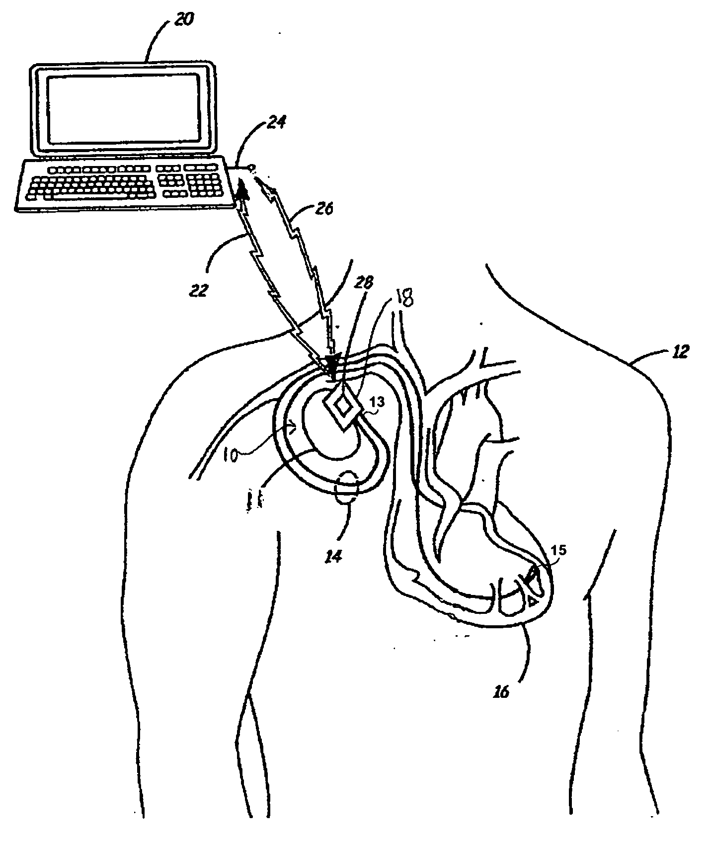
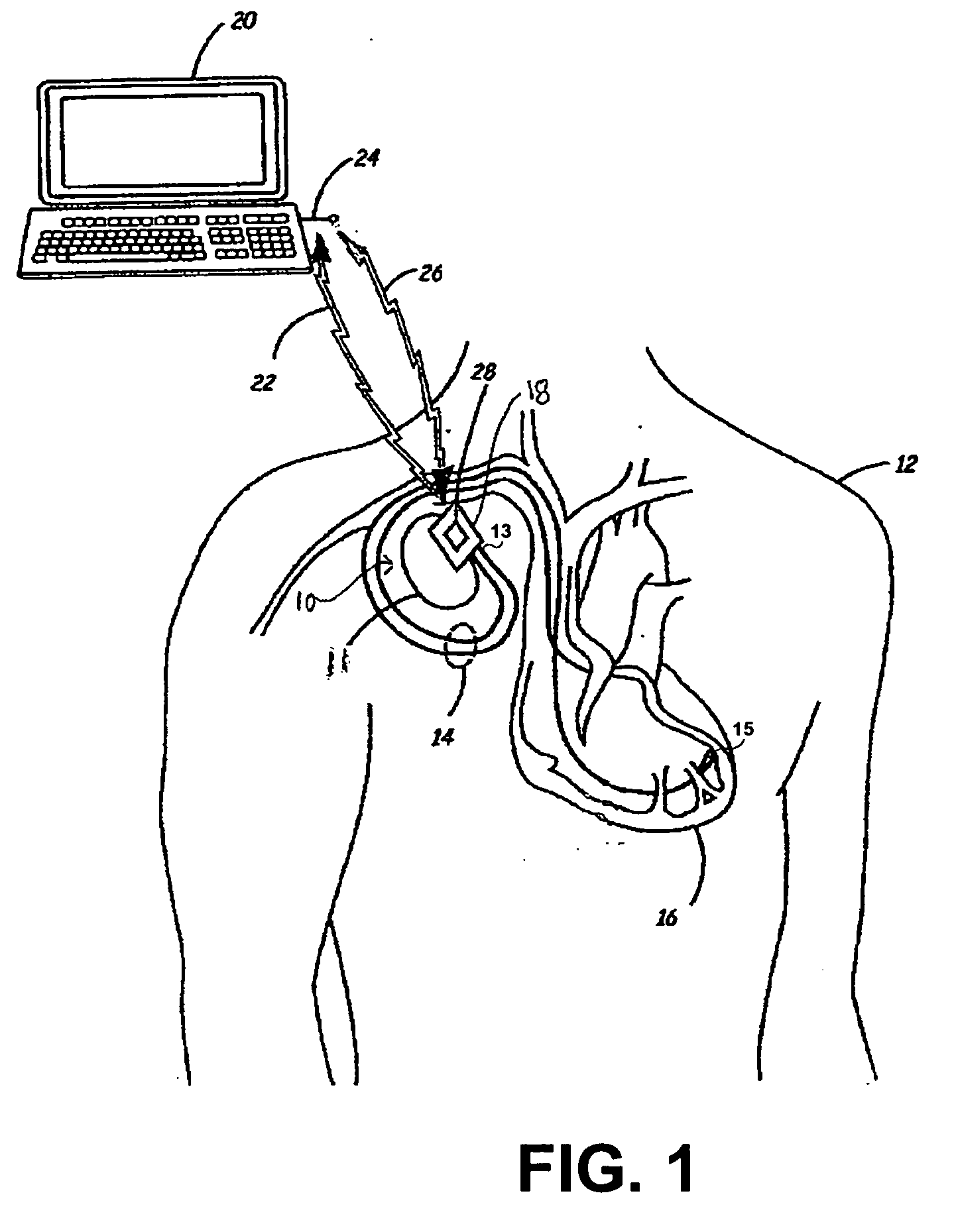
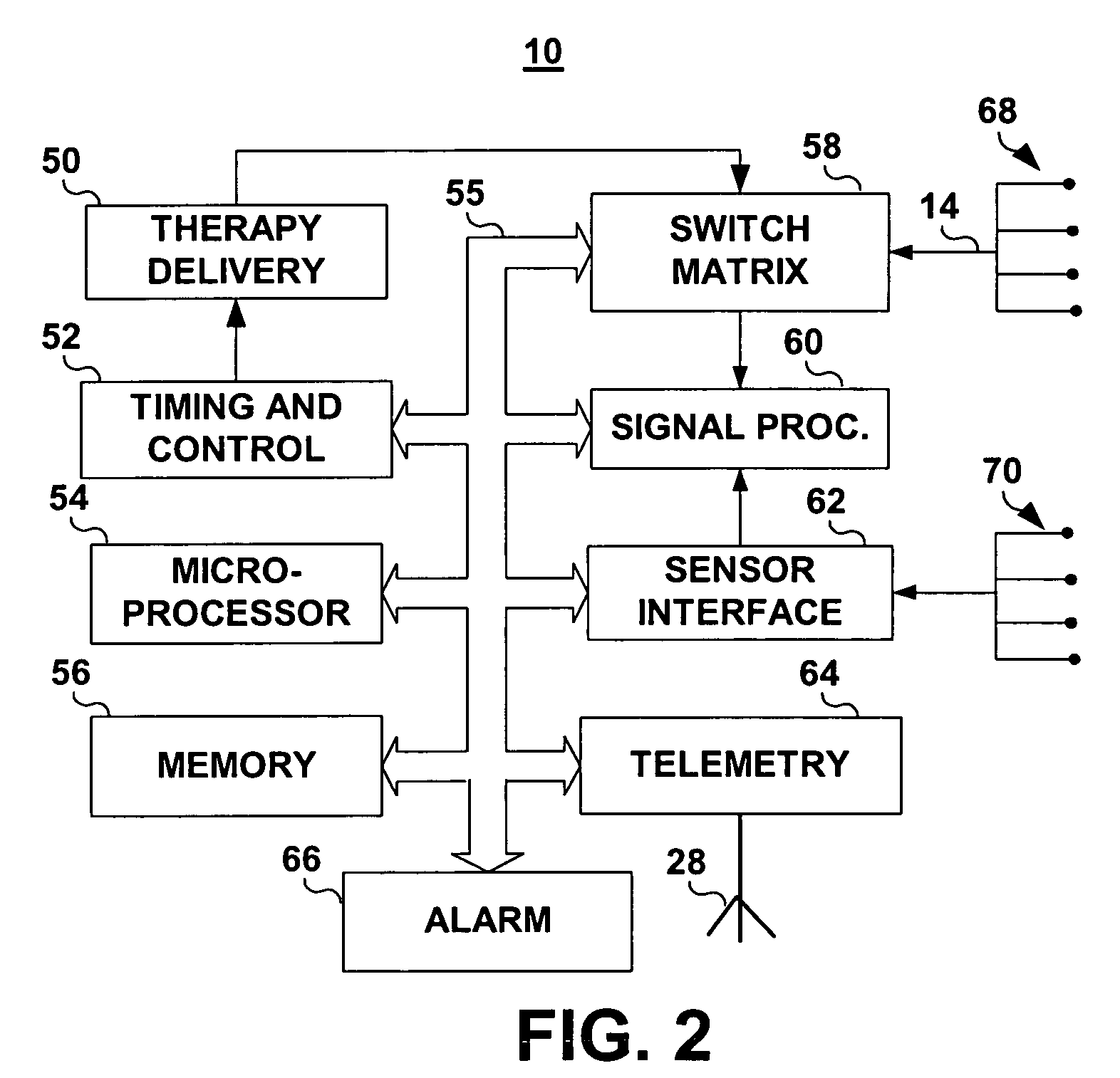
[0005] The associated method includes sampling the telemetry antenna voltage and the lead voltage at desired sampling rates and providing signals corresponding to the respective telemetry antenna and lead voltages. The telemetry antenna voltage and the lead voltage can be measured by sampling onto capacitors and converting the resulting capacitor voltages to digital values. The digital voltage values are compared to MRI detection thresholds defined for the antenna voltage and the lead voltage signals. An MRI detection requirement is predefined based on the frequency and number of MRI detection threshold crossings. If the MRI detection requirement is satisfied, the IMD control circuitry provides a response. Responses may include generating an alarm and / or implementing a set of temporary operating parameters. In one embodiment, an MRI detection response includes a capture test for determining if the energy associated with the induced lead voltage is high enough to capture excitable tissue in contact with an electrode carried by the lead.

Problems solved by technology

Exposure to the strong magnetic field can cause electromagnetic interference (EMI) that can cause improper device function.
IMDs which provide electrical stimulation therapies, such as neurostimuators, cardiac pacemakers and implantable cardioverter defibrillators (ICDs) may inappropriately detect magnetic field induced signals as physiological signals.
Furthermore, magnetic field induced current on lead conductors may result in inappropriate stimulation or heating.
However, this does not prevent inadvertent tissue stimulation due to induced current on stimulation leads.
Furthermore, an IMD programmer and personnel skilled in programming an IMD may not be readily available at the MRI facility.
Scheduling conflicts could result in delays between the programming sessions and the MRI examination which could leave the IMD functioning in a less than optimal operating mode, potentially for several days.
The patient may be left vulnerable to clinical events or conditions normally controlled or treated by the IMD.

Method used


Image

  • Implantable medical device with MRI and gradient field induced capture detection methods
  • Implantable medical device with MRI and gradient field induced capture detection methods
  • Implantable medical device with MRI and gradient field induced capture detection methods

Examples


Embodiment Construction

[0012] The invention is directed toward providing an implantable medical device with the capability of detecting the presence of a strong magnetic field associated with an MRI environment. The invention is further directed toward providing an automatic safeguard response to the detected presence of a magnetic field. Automatic implementation of temporary, “MRI-safe” parameter settings by the IMD in the presence of the MRI environment and the reversal to permanently programmed values outside of the MRI environment allows the “MRI-safe” operation of the IMD to be limited to the time of the MRI examination, while the patient is under medical supervision.

[0013] Aspects of the present invention can improve the safety and performance of any IMD that includes electrical stimulation or sensing of electrical body signals. Such devices include drug pumps, cardiac stimulation devices such as pacemakers and implantable cardioverter defibrillators, and other neuromuscular stimulators, such as de...


PUM


Abstract

An implantable medical device is provided having a telemetry circuit antenna; a lead having an elongated body for carrying a conductor extending from a proximal connector to a distal electrode; a circuit for measuring voltage induced on the telemetry circuit antenna and generating an antenna voltage signal corresponding to the measured voltage on the antenna; a circuit for measuring voltage induced on the lead conductor and generating a lead voltage signal corresponding to the measured voltage on the lead; and processing circuitry for receiving the antenna voltage signal and the lead voltage signal and for generating an MRI detection signal if the antenna voltage signal and the lead voltage signal meet an MRI detection requirement. The device further includes control circuitry for providing a safeguard response to the MRI detection signal.

Description

FIELD OF THE INVENTION [0001] The present invention relates generally to implantable medical devices and in particular to a method and apparatus for detecting electromagnetic interference (EMI) due to magnetic resonance imaging (MRI) equipment and for providing a safeguard response to the detection. BACKGROUND OF THE INVENTION [0002] Patients having an implantable medical device (IMD) may be submitted to MRI examinations for a variety of reasons. Exposure to the strong magnetic field can cause electromagnetic interference (EMI) that can cause improper device function. EMI caused by exposure to an MRI magnetic field can arise on the telemetry antenna included in programmable IMDs and on the leads carrying sensing and stimulation electrodes extending from the IMD. IMDs which provide electrical stimulation therapies, such as neurostimuators, cardiac pacemakers and implantable cardioverter defibrillators (ICDs) may inappropriately detect magnetic field induced signals as physiological s...

Claims


Application Information

Patent Timeline
Patent Type & Authority Applications(United States)
IPC IPC(8): A61B5/05
CPCA61N1/3718A61N1/3706
Inventor WAHLSTRAND, JOHN D.YOUNKER, GREG A.MCCLURE, LAWRENCE C.SAMUELSON, KENTSAWCHUK, ROBERT T.
Owner MEDTRONIC INC
Learn More