Retrieval catheter

a technology of retrieval catheter and tip, which is applied in the field of retrieval catheter and to the tip can solve the problems of buckling of the retrieval catheter tip, difficult to retrieve the relatively large object into the relatively small retrieval catheter tip, and the difficulty of conventional retrieval catheters

Inactive Publication Date: 2006-12-28
SALVIAC
View PDF16 Cites 45 Cited by
  • Summary
  • Abstract
  • Description
  • Claims
  • Application Information

AI Technical Summary

Benefits of technology

[0005] This invention is aimed at providing an improved retrieval catheter which addresses at least some of these problems.

Problems solved by technology

Conventional retrieval catheters suffer from a number of problems.
It is therefore difficult to retrieve the relatively large object into the relatively small retrieval catheter tip.
In addition, retrieval of the large object into the retrieval catheter tip is prone to cause buckling of the retrieval catheter tip due to the large compressive forces acting on the tip during the retrieval process.

Method used


Image

  • Retrieval catheter
  • Retrieval catheter
  • Retrieval catheter

Examples


example 1

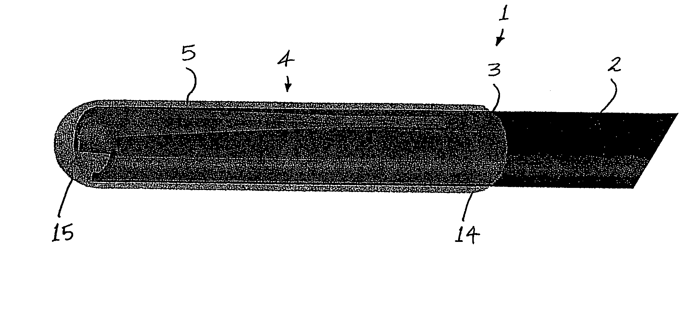
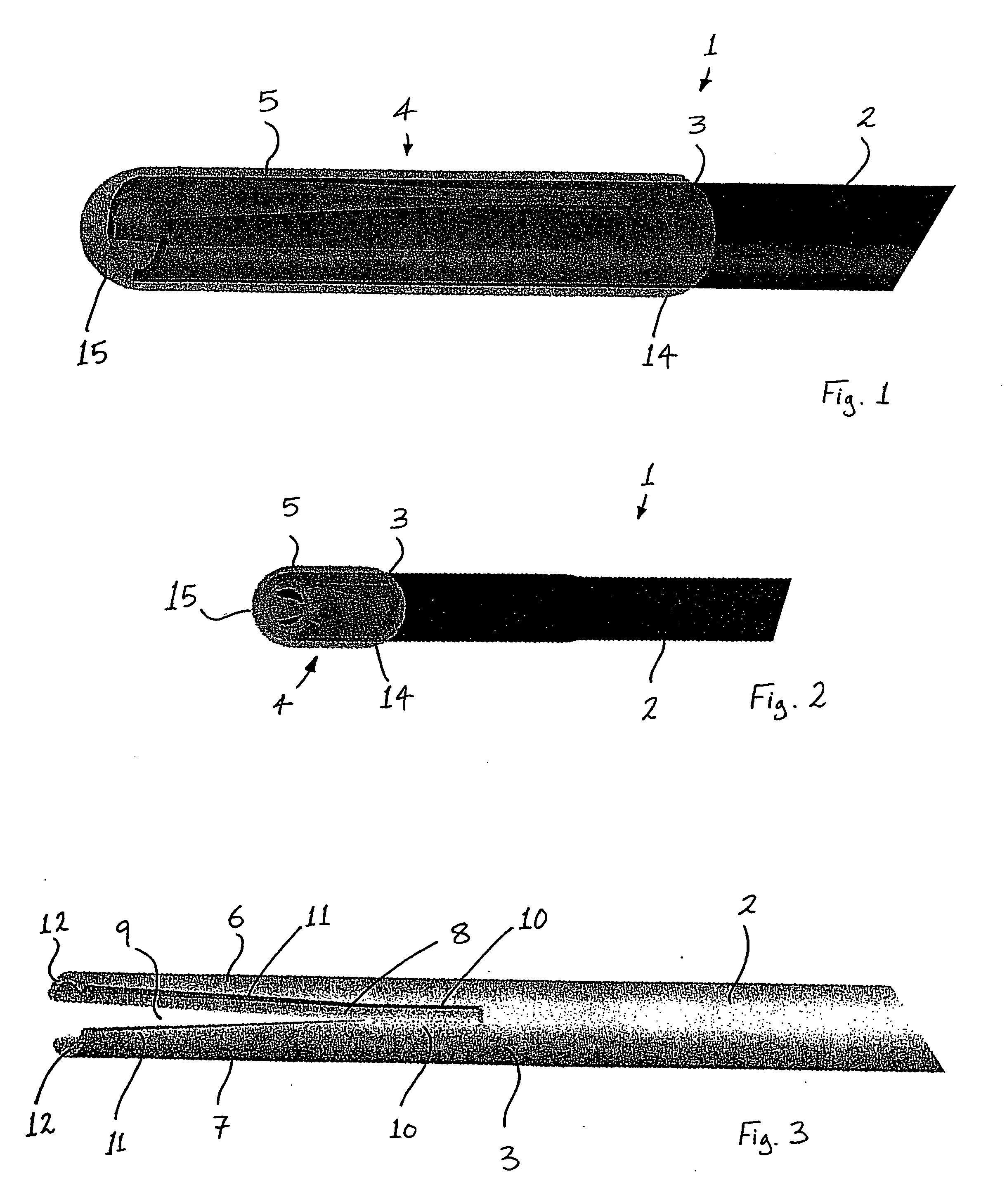
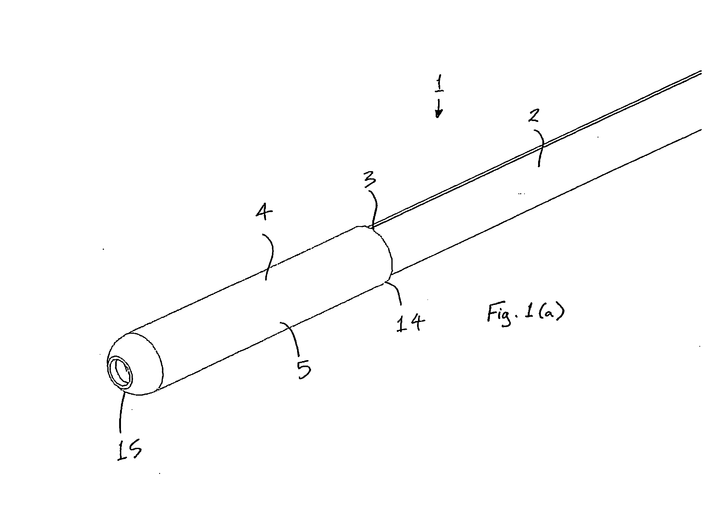
[0244]FIGS. 100-102 show a retrieval catheter tip of this invention. The manner in which the radiopacifying technology of this invention is applied to this tip will be described below. It will be appreciated that the radiopacifying technology of this invention could be applied to many other geometric constructions. This embodiment combines relatively high modulus polymer shaft and splines 1 and a low modulus shaped polymer cuff 2. The shaped polymer cuff 2 is a soft expansile material and it is joined to the splines 1. The soft cuff is radiopacified per this invention. The cuff 2 and splines 1 may be joined by a number of bonding, joining or fusing processes. In this example the cuff 2 and splines 1 are fused. The cuff 2 and splines 1 can expand in the radial direction. The soft material is loaded with a radiopacifier, in this instance tungsten. The tip is loaded with tungsten to 70% by weight. The polymer of the cuff 2 is a low modulus 45A S-EB-S (styrene-ethylene / butylene-styrene)...

example 2

[0254] In this example the MATC for the tip of example 1 will be calculated. The value of l (linear attenuation coefficient) varies with x-ray photon energy, hence the MATC value also varies with photon energy. As described, the photon energy range for interventional x-rays is 50 keV to 100 keV. For the purposes of comparitive disclosure a x-ray photon energy value of 70 keV will be used. [0255] From published information on l and d, the MATC value, for the preferred tip embodiment at 70 keV, can be calculated as: MATCtip={0.3⁢(l / d)S-EB-S+0.70⁢(l / d)Tungsten}×0.04⁢ ⁢cmMATCtip={0.3⁢(0.2)S-EB-S+0.70⁢(11)Tungsten}×0.04⁢ ⁢cmMATCtip=0.311⁢ ⁢cm3⁢ / ⁢g

In an further embodiment of the design, the radiopaque filler is added to the stiffer polymer component (1). In this design the radiopaque filler is compounded with the polymer used to produce the shaft and splines. A schematic of a section A-A through this type of construction is shown in FIG. 104

[0256] In a further embodiment of the design t...


PUM


Abstract

A retrieval catheter (200) comprises a catheter shaft (2) and a retrieval catheter tip at the distal end of the shaft (2). The tip comprises an expandable tip body (201) and two reinforcement columns (6, 7) extending along the tip body (201) embedded within the tip body (201). The tip body (201) comprises a stiff, distal, radiopaque segment (203) and a soft, proximal segment (202). The distal segment (203) has a distal nose part (205) extending distally of the reinforcement columns (6, 7). Along the distal nose part (205), the wall thickness of the tip body (201) tapers distally from a smaller wall thickness to a larger wall thickness, and the internal diameter tapers distally from a larger diameter to a smaller diameter.

Description

RELATED APPLICATION [0001] This application claims the benefit of U.S. Patent Application Ser. No. 60 / 672,300, filed Apr. 18, 2005, the entire teachings of which are incorporated herein by reference.INTRODUCTION [0002] This invention relates to a retrieval catheter and to a retrieval catheter tip into which an object may be retrieved. [0003] It is known to insert a retrieval catheter into a body passageway of a patient, and to advance the retrieval catheter through the body passageway to retrieve an object, such as an embolic protection filter, from the passageway into the retrieval catheter. During advancement of the retrieval catheter through the body passageway, the retrieval catheter tip must present a low profile to facilitate advancement through the potentially narrow and / or tortuous passageway, and also to avoid causing damage or discomfort to the patient. [0004] Conventional retrieval catheters suffer from a number of problems. Generally the object to be retrieved from the b...

Claims


Application Information

Patent Timeline
Patent Type & Authority Applications(United States)
IPC IPC(8): A61B17/22
CPCA61B17/22031A61B17/221A61B19/54A61L29/18A61B2017/2215A61F2002/011A61B2017/22035A61B90/39A61F2/011
Inventor FAHEY, GARYKELLY, RONALDGRIFFIN, PATRICKBRADY, EAMONVALE, DAVIDNEILAN, JOHN
Owner SALVIAC
Why Eureka
Try Eureka