Automated and adaptive threshold setting

Inactive Publication Date: 2006-12-28
SERVICENOW INC
View PDF9 Cites 81 Cited by
  • Summary
  • Abstract
  • Description
  • Claims
  • Application Information

AI Technical Summary

Benefits of technology

[0025] automatically adjusting the component performance threshold responsively to the

Problems solved by technology

Setting such meaningful values of component-level performance thresholds is a complicated task, especially in c

Method used


Image

  • Automated and adaptive threshold setting
  • Automated and adaptive threshold setting
  • Automated and adaptive threshold setting

Examples


Embodiment Construction

System Description

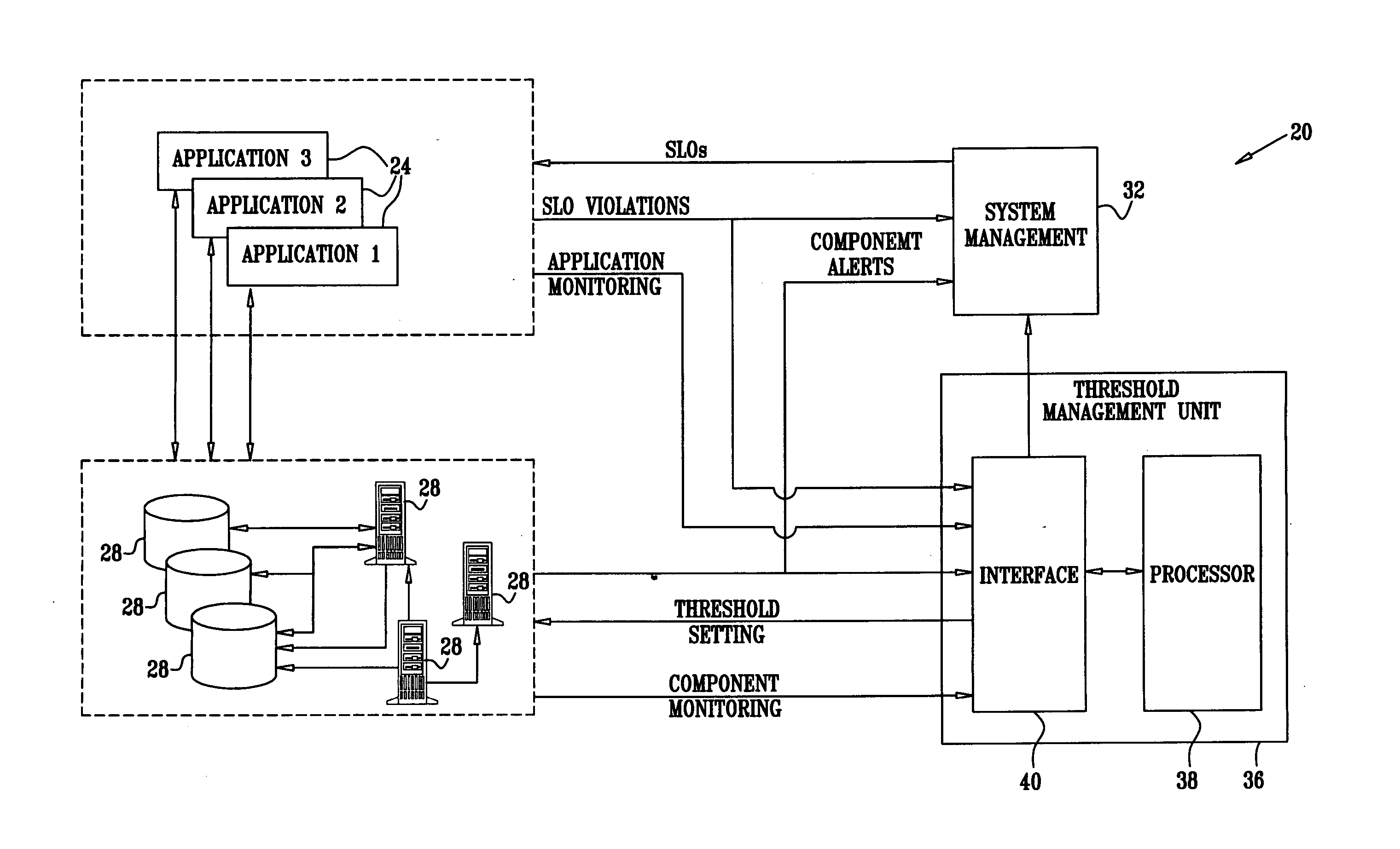
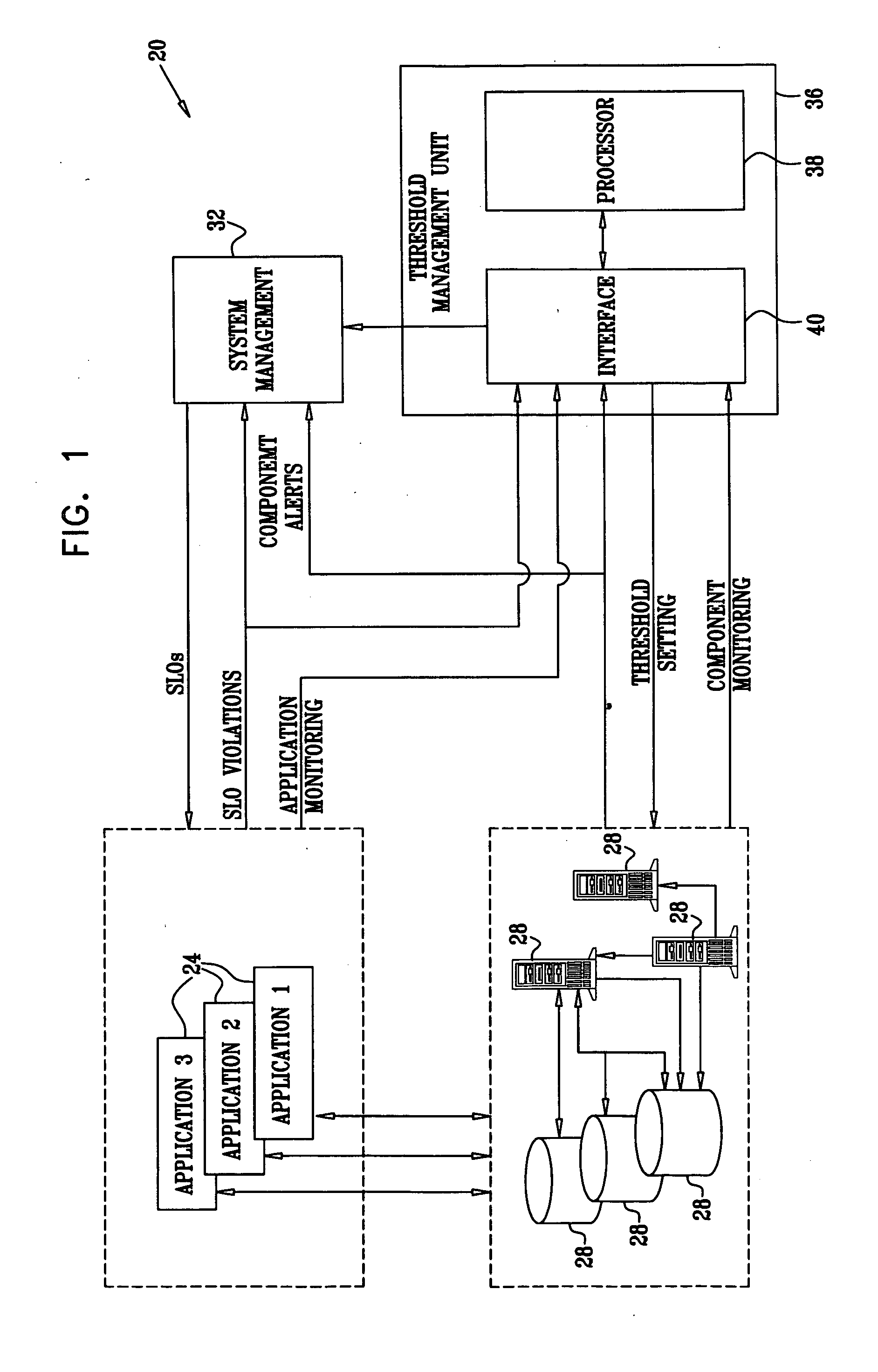
[0048]FIG. 1 is a block diagram that schematically illustrates a computer system 20, in accordance with an embodiment of the present invention. System 20 may comprise, for example, a storage-area network (SAN) that interconnects multiple servers to multiple storage devices. Alternatively, system 20 can comprise an enterprise computer system, an electronic business system, a web-site or any other suitable computer system. In some embodiments, system 20 employs autonomous computing and / or self-management methods, as are known in the art. Software applications 24 run on system components 28. Components 28 may comprise, for example, storage devices such as disks or tapes, disk arrays and their controllers, computing platforms such as servers, and communication devices such as switches and routers. Components 28 are interconnected using suitable interconnection means, such as a backplane or a local area network (LAN), and communicate with each other and with applicatio...


PUM


Abstract

A method for managing a computer system includes monitoring first violations of a service level objective (SLO) of a service running on the computer system so as to determine a first statistical behavior of the first violations. Second violations of a component performance threshold of a component of the computer system are monitored so as to determine a second statistical behavior of the second violations. A model that predicts the second statistical behavior based on the first statistical behavior is produced. The component performance threshold is automatically adjusted responsively to the model, so as to improve a prediction of the first violations by the second violations.

Description

CROSS-REFERENCE TO RELATED APPLICATIONS [0001] This application is related to U.S. patent application Ser. No. 11 / 088,054, entitled “Root-Cause Analysis of Network Performance Problems,” filed on Mar. 23, 2005. This related application is assigned to the assignee of the present patent application and is incorporated herein by reference.FIELD OF THE INVENTION [0002] The present invention relates generally to computer system management, and particularly to methods and systems for automated and adaptive setting of system component performance thresholds. BACKGROUND OF THE INVENTION [0003] Computer systems commonly use performance thresholds for monitoring and managing the performance of system components. Threshold violations are recorded and analyzed as possible indicators of system faults. Various methods for setting and managing component performance thresholds (referred to herein as “component thresholds” for brevity) are known in the art. For example, Hellerstein et al. describe a...

Claims


Application Information

Patent Timeline
IPC IPC(8): G06F19/00
CPCH04L12/24H04L41/00H04L41/147H04L43/16H04L41/5009H04L43/08H04L41/5003H04L41/149
Inventor BREITGAND, DAVIDHENIS, EALANSHEHORY, ONN
Owner SERVICENOW INC
Why Eureka
Try Eureka