
Method and apparatus for managing a link return stack

a technology of link return stack and return address, applied in the field of microprocessors, can solve the problems of link return stack holding one or more invalid return addresses, affecting machine performance and power efficiency, etc., and achieve the effect of avoiding power consumption

Inactive Publication Date: 2006-12-28
STEMPEL BRIAN MICHAEL +3
View PDF4 Cites 9 Cited by
  • Summary
  • Abstract
  • Description
  • Claims
  • Application Information

AI Technical Summary

Benefits of technology

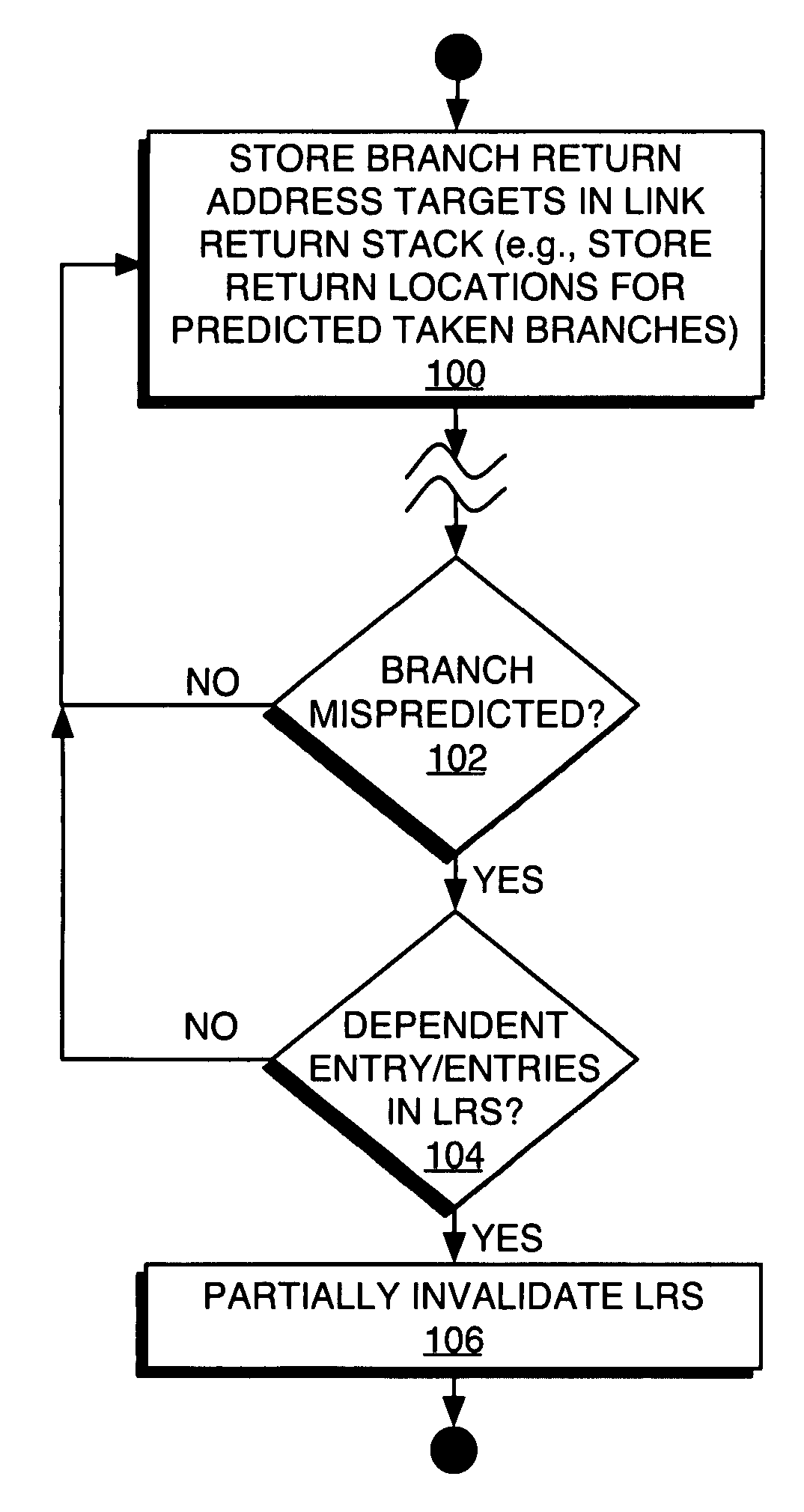
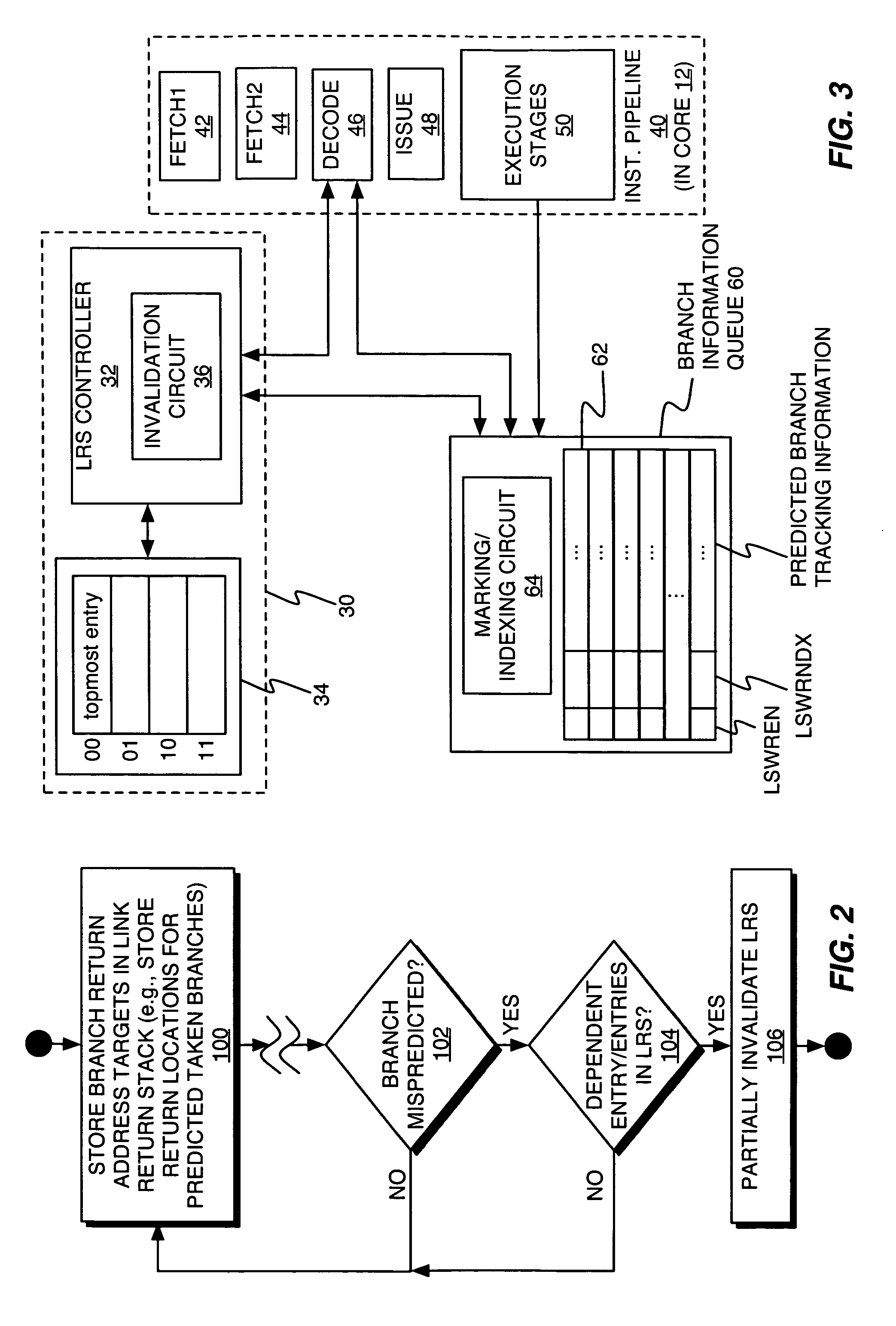
[0010] The present invention comprises a method and apparatus for managing a link return stack used for storing branch return addresses based on partially invalidating the link return stack responsive to detecting a mispredicted branch. In at least one embodiment, partially invalidating the link return stack comprises invalidating entries in the link return stack that are dependent on the mispredicted branch, and resetting the link return stack to a remaining valid entry. Doing so provides the microprocessor with the branch return performance improvements gained by retaining the valid branch return addresses remaining in the link return stack, while avoiding the power consumption the processor otherwise would waste by accessing its instruction cache at the invalid branch return addresses.

Problems solved by technology

Processors targeted for battery-powered portable devices, such as music players, palmtop computers, Portable Digital Assistants (PDAs), and the like, represent a particularly complex mix of competing design considerations.
However, branch prediction operations introduce potential link return stack problems.
In general, then, branch mispredictions result in the link return stack holding one or more invalid return addresses.
The number of erroneous entries in the link stack may dwindle over time as the older, invalid entries drop off, but prefetching from erroneous addresses harms both machine performance and power efficiency.
One alternative to the above “method” avoids wasting power but, ultimately, forfeits at least some of the performance gains afforded by the link return stack.

Method used


Image

  • Method and apparatus for managing a link return stack
  • Method and apparatus for managing a link return stack
  • Method and apparatus for managing a link return stack

Examples


Embodiment Construction

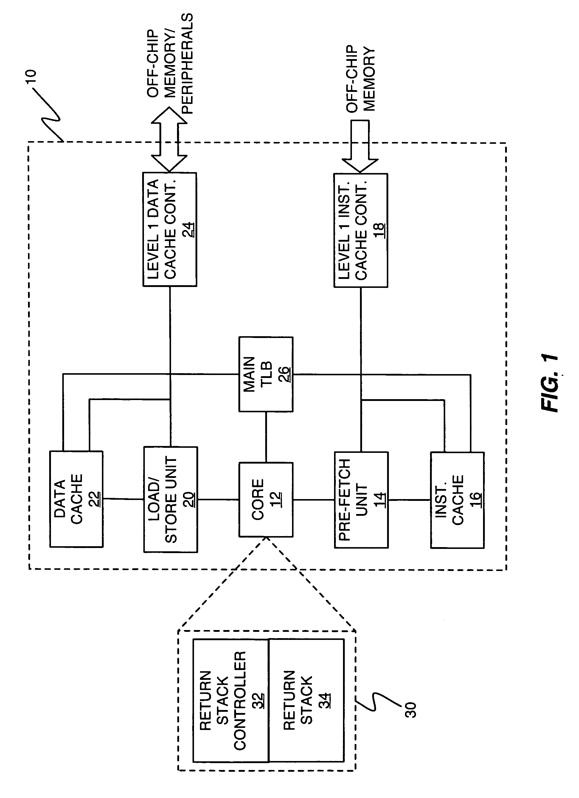
[0023]FIG. 1 at least partially illustrates a microprocessor 10 comprising a processor core 12, an instruction pre-fetch unit 14, an instruction cache 16, an instruction cache controller 18, a load / store unit 20, a data cache 22, a data cache controller 24, and a main translation lookaside buffer 26. In at least one embodiment, the processor 10 includes a link return stack circuit 30 comprising a link return stack controller 32 and a link return stack 34 (e.g., registers or other memory locations). By way of non-limiting example, the microprocessor 10 may be a pipelined processor based on a Reduced Instruction Set Computer (RISC) architecture.

[0024] In one or more embodiments, the core 12 includes an instruction execution unit (not shown) comprising one or more multi-stage instruction pipelines. In operation, the core 12 executes program instructions and carries out corresponding load / store data operations. The translation lookaside buffer 26 accepts inputs from the core 12 and pro...


PUM


Abstract

In one or more embodiments, a processor includes a link return stack circuit used for storing branch return addresses, wherein a link return stack controller is configured to determine that one or more entries in the link return stack are invalid as being dependent on a mispredicted branch, and to reset the link return stack to a valid remaining entry, if any. In this manner, branch mispredictions cause dependent entries in the link return stack to be flushed from the link return stack, or otherwise invalidated, while preserving the remaining valid entries, if any, in the link return stack. In at least one embodiment, a branch information queue used for tracking predicted branches is configured to store a marker indicating whether a predicted branch has an associated entry in the link return stack, and it may store an index value identifying the specific, corresponding entry in the link return stack.

Description

BACKGROUND [0001] 1. Field of the Invention [0002] The present invention generally relates to microprocessors, and particularly relates to managing hardware link return stacks used by some types of microprocessors for accelerating returns from procedure calls. [0003] 2. Relevant Background [0004] Microprocessors find use in a wide variety of products, ranging from high-end computational systems, where processing power represents a paramount design consideration, to low-end embedded systems, where cost, size, and power consumption comprise the primary design considerations. Processors targeted for battery-powered portable devices, such as music players, palmtop computers, Portable Digital Assistants (PDAs), and the like, represent a particularly complex mix of competing design considerations. On the one hand, processor performance must be sufficient to support the device's intended functionality and provide a satisfactory user “experience.” On the other hand, processor power consumpt...

Claims


Application Information

Patent Timeline
IPC IPC(8): G06F15/00
CPCG06F9/3806G06F9/30054G06F9/3861G06F9/3842
Inventor STEMPEL, BRIAN MICHAELDIEFFENDERFER, JAMES NORRISSARTORIUS, THOMAS ANDREWSMITH, RODNEY WAYNE
Owner STEMPEL BRIAN MICHAEL
Learn More