Method and system for regeneration of a catalyst

Inactive Publication Date: 2007-01-04
GENERAL ELECTRIC CO
View PDF4 Cites 39 Cited by
  • Summary
  • Abstract
  • Description
  • Claims
  • Application Information

AI Technical Summary

Benefits of technology

[0005] Briefly, in accordance with one embodiment of the invention, there is provided a system for regeneration of a catalyst. The system includes an engine that creates an exhaust stream, a fuel supply adapted to supply a fuel stream to the engine, a reactor that includes a catalyst and is in fluid communication with the engine to receive the exhaust stream and a sensor that senses a system parameter and produces a signal corresponding to the system parameter. The system also includes a controller that receives the signal and directs at least a portion of the exhaust stream or at least a portion of the fuel stream to the catalyst to control a regeneration operation based on a valu

Problems solved by technology

However, in such traditional catalyst systems, soot, hydrocarbons, and other undesirable species may adsorb on the surface of the catalyst, thus contaminating the catalyst and reducing its conversion efficiency.
Known met

Method used


Image

  • Method and system for regeneration of a catalyst
  • Method and system for regeneration of a catalyst
  • Method and system for regeneration of a catalyst

Examples


Embodiment Construction

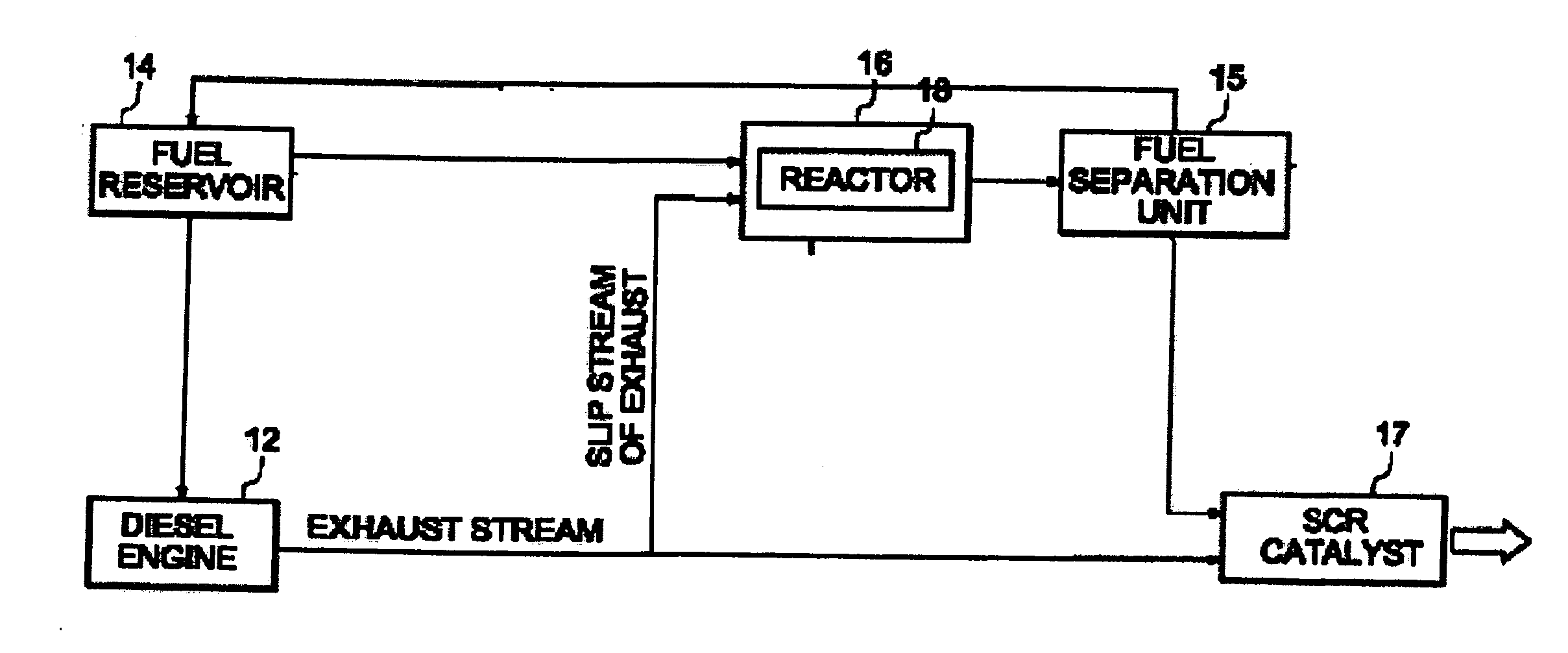
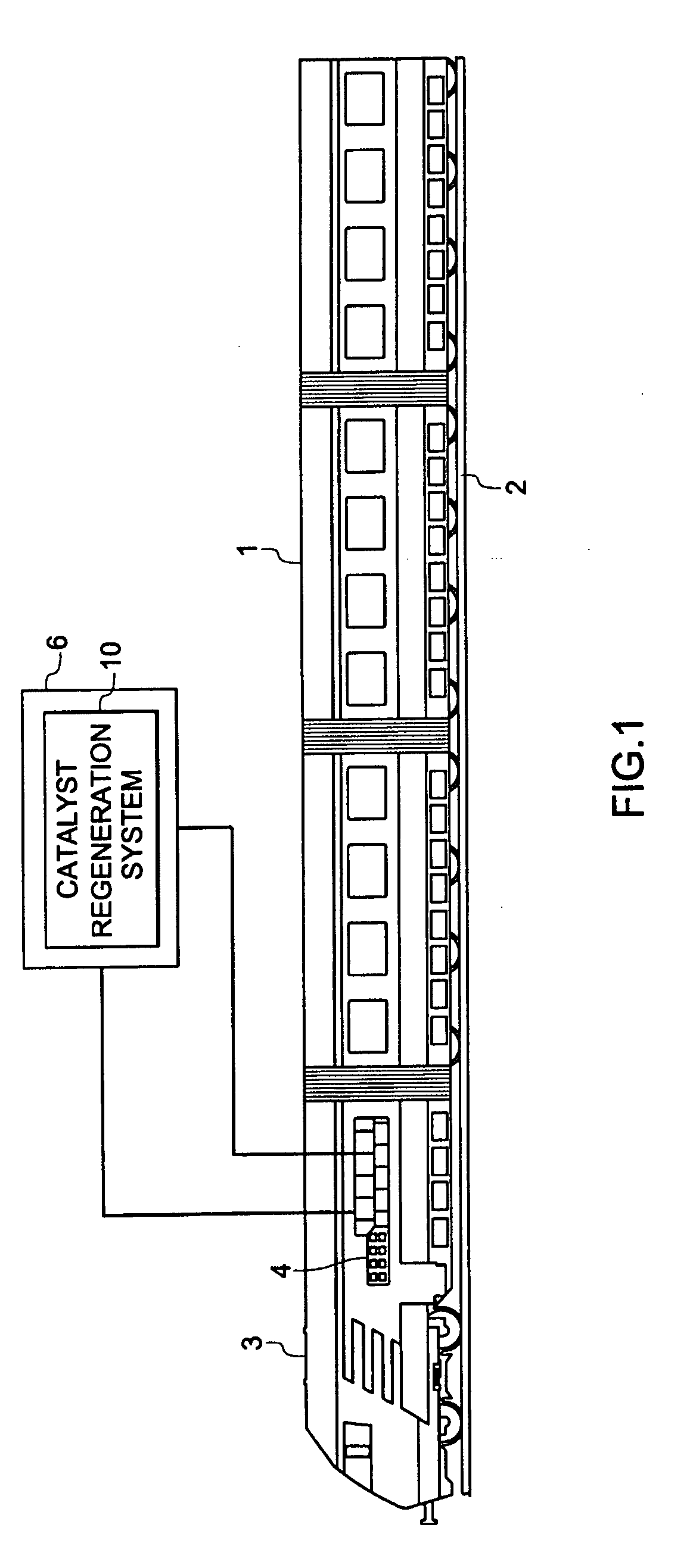
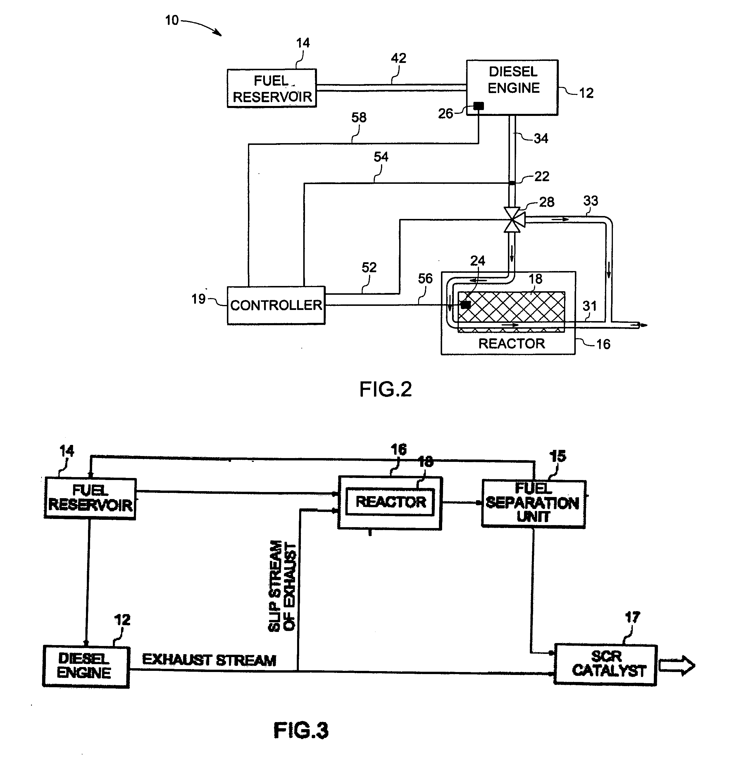
[0012]FIG. 1 is a schematic diagram of a railroad locomotive that uses an exemplary system for regeneration of catalyst in a diesel engine exhaust treatment system in accordance with one embodiment of the present technique. A train 1 runs on a rail 2. A locomotive 3 includes a diesel engine 4 to drive the train 1. The locomotive 3 is equipped with an exhaust treatment system 6 to treat the exhaust coming out from the engine 4. The exhaust treatment system 6 includes catalyst used for exhaust treatment. The locomotive 3 also includes a system 10 for regeneration of the catalyst in exhaust treatment system 6. Although FIG. 1 shows a locomotive, those of ordinary skill in the art will appreciate the applicability of the present technique to other systems that employ catalyst. For example, the present technique may be employed in other vehicles that have combustion engines, such as passenger vehicles, buses, ships, off-road vehicles, stationary devices such as generators and boilers or ...


PUM


Abstract

The disclosed embodiments relate to a method and system for regeneration of a catalyst. The system includes an engine that creates an exhaust stream and a fuel supply adapted to supply a fuel stream to the engine. A reactor includes a catalyst and is in fluid communication with the engine to receive the exhaust stream. A sensor senses a system parameter and produces a signal corresponding to the system parameter. A controller receives the signal and directs at least a portion of the exhaust stream or at least a portion of the fuel stream to the catalyst to control a regeneration operation based on a value of the system parameter sensed by the sensor.

Description

BACKGROUND [0001] The present invention relates to a system and a method for improving performance of an exhaust gas after-treatment system, and more particularly to regenerating a catalyst to improve its NOx conversion efficiency. [0002] Current emission control regulations necessitate the use of catalysts in the exhaust systems of automotive vehicles in order to convert carbon monoxide (CO), hydrocarbons (HC), and nitrogen oxides (NOx) produced during engine operation into harmless exhaust gasses. Vehicles equipped with diesel or lean gasoline engines offer the benefit of increased fuel economy. Such vehicles can benefit from exhaust after-treatment systems that employ one or more catalysts to assist in chemically converting NOx, hydrocarbons, carbon monoxide, and other pollutants into less harmful compounds prior to discharge of the exhaust to the environment. [0003] However, in such traditional catalyst systems, soot, hydrocarbons, and other undesirable species may adsorb on the...

Claims


Application Information

Patent Timeline
IPC IPC(8): F01N3/00
CPCB01D53/9409Y02T10/24B01D2258/012B61C17/00F01N3/2066F01N2240/30F01N2250/12F01N2260/04F01N2410/00F01N2430/08F01N2550/03F01N2590/08F01N2610/04Y02T30/10B01D53/9495Y02T30/00Y02T10/12
Inventor LIU, KEMALE, JONATHAN LLOYDFRYDMAN, ARNALDOPRIMUS, ROY JAMESZAMANSKY, VLADIMIRROCHA, TERESA GROCELA
Owner GENERAL ELECTRIC CO
Why Eureka
Try Eureka