
Chromatography system with waste output

a chromatography system and waste output technology, applied in the field of chromatography, can solve problems such as affecting the analysis of samples (i.e., mixtures of components), and achieve the effects of optimizing the intake stroke, avoiding channel cross flow, and optimizing the delay volum

Active Publication Date: 2007-01-04
AGILENT TECH INC
View PDF33 Cites 17 Cited by
  • Summary
  • Abstract
  • Description
  • Claims
  • Application Information

AI Technical Summary

Benefits of technology

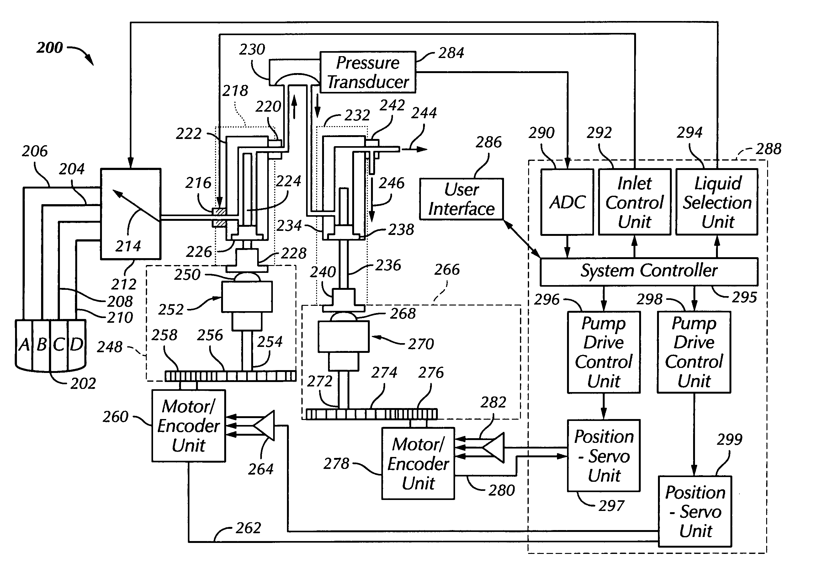
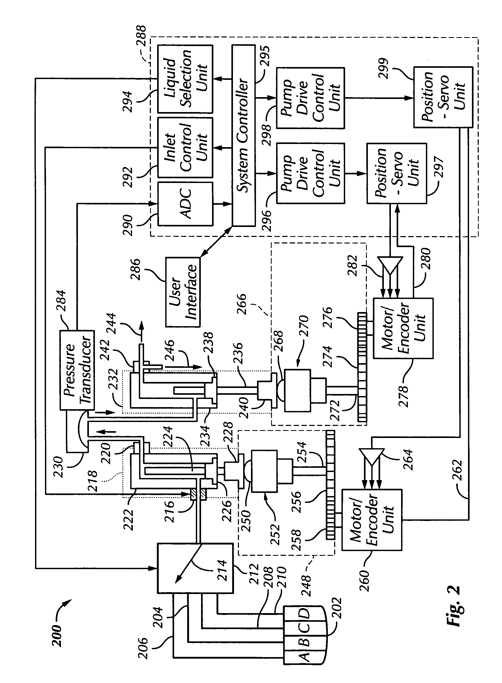
[0010] It is an object of the invention to provide an improved chromatography system. A variety of methods and apparatus for operating a pumping system are presented. Among these methods and apparatus are a pumping apparatus with a variable concept for flow generation dependent on a required flow rate; a method for determining and compensating for leaks in piston pumps; a method for calibrating a mass flow sensor; a method for avoiding channel cross flow in multiple channel pumping systems; a pumping method and apparatus with optimized delay volume; a pumping method and apparatus with optimized intake stroke; and a pumping method and apparatus with improved piston timing.

Problems solved by technology

However, there are a number of problems that arise when processing liquid through the chromatography system.
The problems impact the flow of liquid through the chromatography system and as a result, impact the analysis of the sample (i.e., mixtures of components).
For example, varying the flow of liquid through a pump affects the analysis of the sample in a chromatography system; leaks may affect the flow of liquid through a chromatography system; incorrectly calibrated devices, such as sensor(s), may affect the flow of liquid through a chromatography system; cross over of liquids in a pumping system with multiple channels may affect the flow of liquid through a chromatography system; discontinuities in a liquid may affect the flow of liquid through a chromatography system; the intake operation of the pump may affect the flow of liquid through a chromatography system; and the piston timing of a pump may affect the flow of liquid through a chromatography system.

Method used


Image

  • Chromatography system with waste output
  • Chromatography system with waste output
  • Chromatography system with waste output

Examples


second embodiment

[0153] In a second embodiment, a test is made to determine the tightness of the pumping unit 934. The liquid stored in the pumping unit 934 is metered out of the chamber 936 and through the flow sensor 942. The calibration curve for a known solvent 1136 is provided (e.g., by the manufacturer). The voltage of a known solvent 1138 at a known flow rate 1142 is identified. An unknown solvent 1140, such as liquid 922A, liquid 922B, liquid 922C, and liquid 922D, is then processed through flow sensor 942 at a known flow rate 1142. The calibration factor 1144 is then defined as the ratio of voltage of the unknown solvent 1140 to the voltage of the known solvent 1138. This method may be performed at different flow rates.

third embodiment

[0154] In a third embodiment, a test is made to determine the tightness of the pumping unit 920 and the pumping unit 934. The liquid stored in the pumping unit 920 is metered out of the chamber 922 and through the flow sensor 932, through the chamber 936, and through the flow sensor 942. The liquid stored in the pumping unit 934 is metered out of the chamber 936 and through the flow sensor 942. The calibration curve for a known solvent 1136 is provided (e.g., by the manufacturer). The voltage of a known solvent 1138 at a known flow rate 1142 is identified. An unknown solvent 1140, such as liquid 922A, liquid 922B, liquid 922C, and liquid 922D, is then processed through flow sensor 942 at a known flow rate 1142. The calibration factor 1144 is then defined as the ratio of voltage of the unknown solvent 1140 to the voltage of the known solvent 1138. This method may be performed at different flow rates.

[0155]FIG. 9B will be discussed in conjunction with FIG. 11C. At 1130 of FIG. 11C, th...


PUM

PropertyMeasurementUnit
stroke volumeaaaaaaaaaa
flow rateaaaaaaaaaa
pressureaaaaaaaaaa

Abstract

A variety of methods for operating a chromatography system are presented. Specifically, methods for operating a pumping system within a chromatography system are presented. The methods presented are directed to pumping apparatus in which very small amounts of fluid are pumped through the system. A number of techniques for detecting and compensating for leaks are presented as well as a number of techniques for operating the pumping system.

Description

[0001] This application claims priority from PCT Application No. PCT / EP2003 / 050794, filed on Nov. 5, 2003.FIELD OF THE INVENTION [0002] Chromatography systems perform a broad range of analysis methods to separate and / or analyze complex mixtures. There are a number of different types of chromatography systems, such as gas chromatography systems, Ion exchange chromatography systems, affinity chromatography systems, liquid chromatography systems, etc. In each type of chromatography system, components of a mixture are separated and distributed between two phases known as a mobile phase and a stationary phase. DISCUSSION OF THE BACKGROUND ART [0003] During operation, a mixture of various components is processed through a chromatography system at different rates. The different rates of migration through the chromatography system facilitate the separation of the mixture. Once the separation is accomplished, the different components of the mixture may be analyzed. [0004] One conventional ty...

Claims


Application Information

Patent Timeline
Patent Type & Authority Applications(United States)
IPC IPC(8): G01N30/36F04B49/00G01M99/00
CPCG01N30/36G05D11/132Y10T137/85986
Inventor WEISSGERBER, HANS-GEORG
Owner AGILENT TECH INC
Learn More