Steering systems

a steering system and steering wheel technology, applied in the field of utility vehicles, can solve problems such as not allowing direct conclusions regarding

Inactive Publication Date: 2007-01-04
AGCO GMBH
View PDF8 Cites 12 Cited by
  • Summary
  • Abstract
  • Description
  • Claims
  • Application Information

AI Technical Summary

Benefits of technology

[0011] Arranging the ball according to claim 8 in an end region of the bolt allows the provision of a compact ball-and-socket joint in which the steering angle sensor may be accommodated in ve

Problems solved by technology

Known devices of this type are based on determining the position of components of the steering linkage, for example the piston in the steering cylinder, and, on account of the complex mec

Method used


Image

  • Steering systems
  • Steering systems
  • Steering systems

Examples


Embodiment Construction

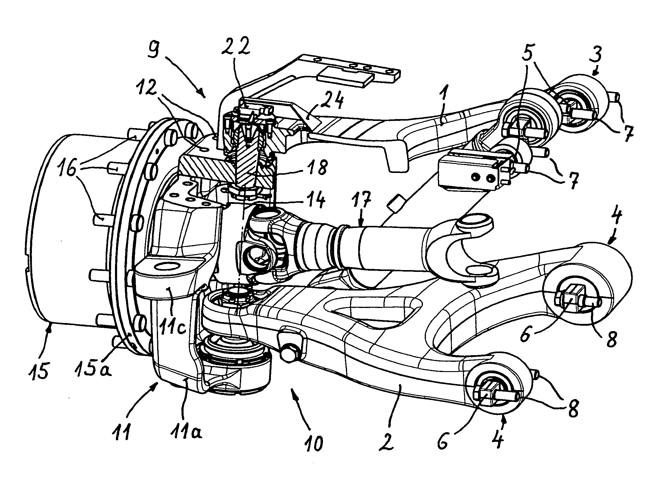
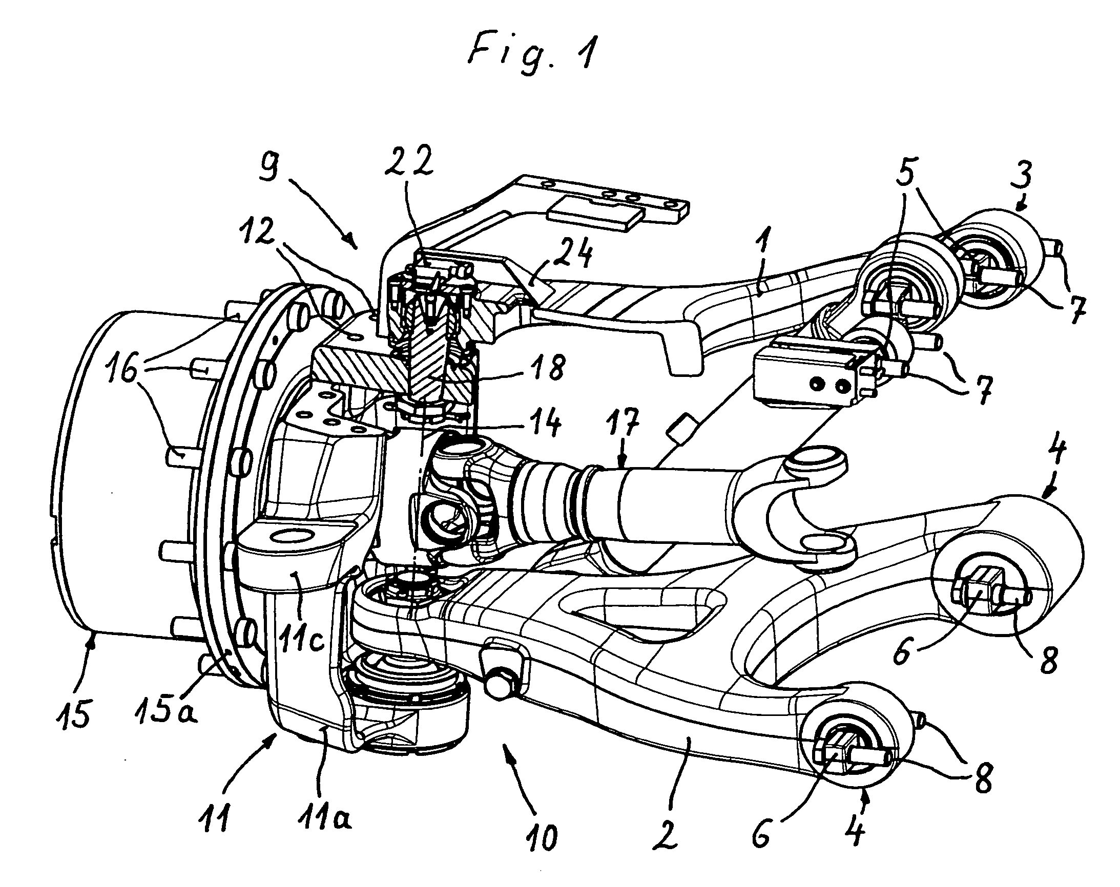
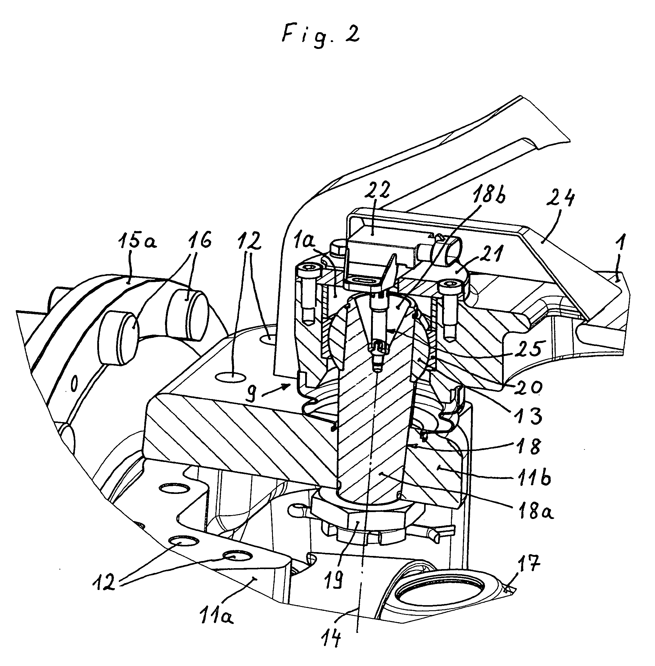
[0018] The wheel suspension shown in FIG. 1 for the steering wheel of the right-hand vehicle side comprises an upper transverse suspension element 1 and a lower transverse suspension element 2. Both transverse suspension elements 1, 2 are pivotally mounted via joints 3, 4 on the vehicle bodywork (not shown). The axles 5, 6 of the joints 3, 4 extend substantially horizontally in the vehicle longitudinal direction and are fastened to the vehicle bodywork by means of screws 7, 8. The upper transverse suspension element 1 is connected to a wheel carrier 11 via an upper ball-and-socket joint 9 accommodated in its free end region. Said wheel carrier has a lower principal part 11a, in the lower region of which a ball-and-socket joint 10 required for the attachment of the lower transverse suspension element 2 is mounted. An upper covering plate 11b, which is screwed to the principal part 11a at 12 is connected to the ball 13 of the ball-and-socket joint 9, which is associated with the upper...


PUM


Abstract

The invention discloses a utility vehicle, in particular an agricultural tractor, with a steering system having single-wheel-suspended steering wheels, which are mounted on a respective wheel carrier (11). Each wheel carrier (11) may be swivelled about the axis of at least one rigidly connected bolt (18) and is connected via a ball-and-socket joint (9) on the at least one bolt, to a transverse steering element (1) that is articulated to the vehicle body.
Associated with the ball-and-socket joint (9) is a steering angle sensor (22) comprising a rotatable input member (23), which is located at least approximately in the extension of the axis of the swivel bolt (18). The rotatable input member (23) is connected to the bolt via an entrainment element (25) that transmits the swivel motion of the bolt in an angularly precise manner to detect the current swivel position of the wheel carrier (11).

Description

BACKGROUND OF THE INVENTION [0001] The invention relates to a utility vehicle, in particular an agricultural tractor, with a steering system having single-wheel-suspended steering wheels, which are mounted on a respective wheel carrier, wherein each wheel carrier may be swivelled about the axis of at least one rigidly connected bolt which is connected via a ball-and-socket joint, to a transverse suspension element that is articulated to the vehicle body. [0002] U.S. Pat. No. 5,538,274 describes a utility vehicle having a single-wheel suspension system for the steering wheels. The steering wheels are each mounted on a wheel carrier, which is connected via two ball-and-socket joints to an upper and a lower transverse suspension element. The transverse suspension elements are pivotally mounted on the vehicle frame and guide the wheel carrier during vertical movement of the suspension elements relative to the body vehicle. The ball-and-socket joints allow not only the suspension movemen...

Claims


Application Information

Patent Timeline
IPC IPC(8): B62D7/18B62D7/16B62D15/02
CPCB60G3/24B60G2200/144B60G2200/44B60G2204/11B60G2204/416Y10T403/20B62D7/18B62D15/021B62D15/023Y10T403/32196Y10T403/32631B62D7/16B60G2300/082F16C11/06
Inventor FREYTAG, ERICHGLASER, BERND
Owner AGCO GMBH
Why Eureka
Try Eureka