Braking force generator for a hydraulic vehicle braking system

a technology for hydraulic vehicles and generators, applied in brake action initiation, brake systems, transportation and packaging, etc., can solve problems such as increased susceptibility to faults, increased technical outlay, and displacement of movable walls

Inactive Publication Date: 2007-01-04
LUCAS AUTOMOTIVE GMBH
View PDF10 Cites 22 Cited by
  • Summary
  • Abstract
  • Description
  • Claims
  • Application Information

AI Technical Summary

Benefits of technology

[0007] The present invention generally provides a brake force generator of the initially described type, which, while being of a relatively simple and economical design, is extremely reliable and guarantees a reliable braking effect even in the event of the failure of individual components.
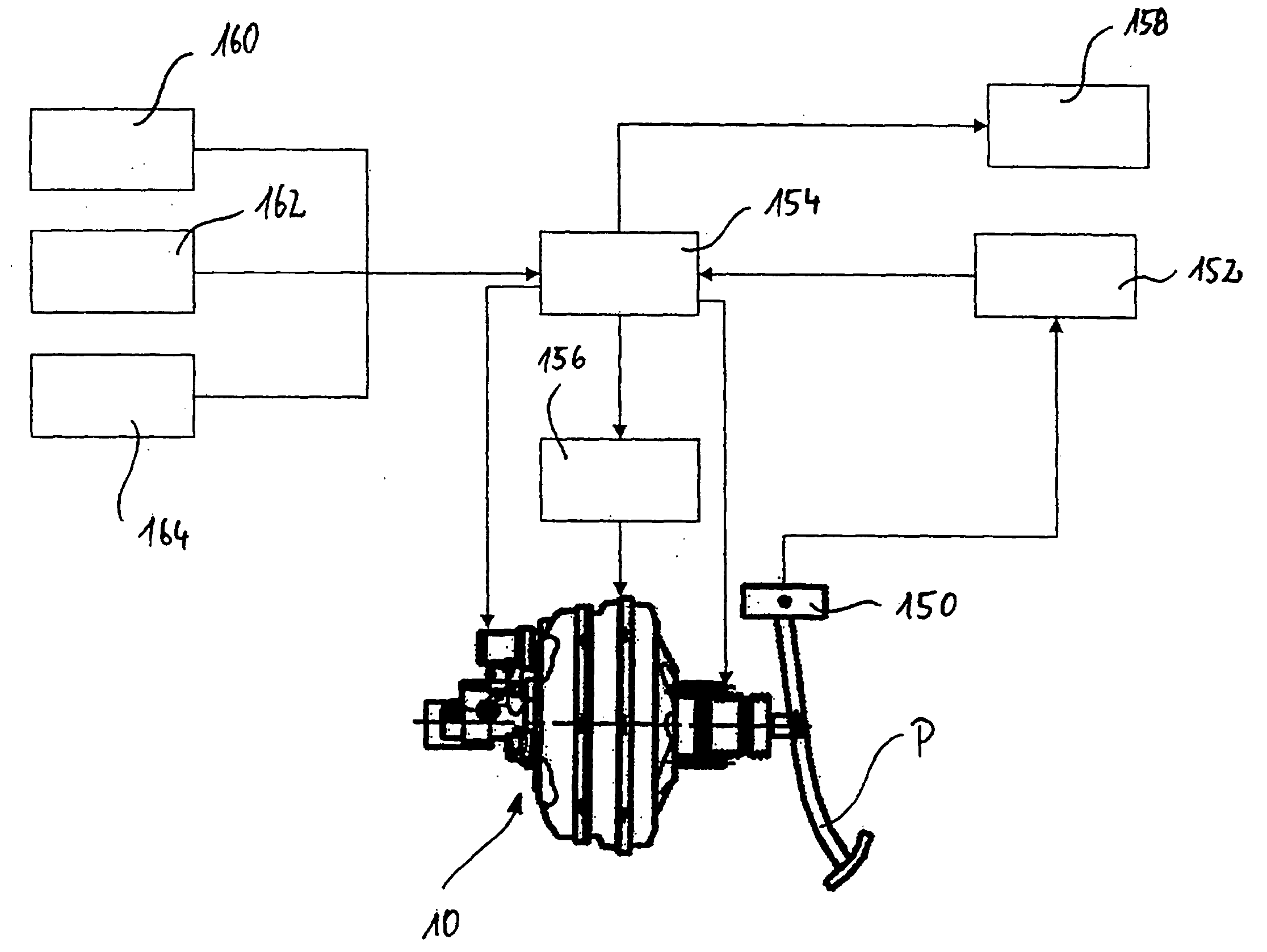
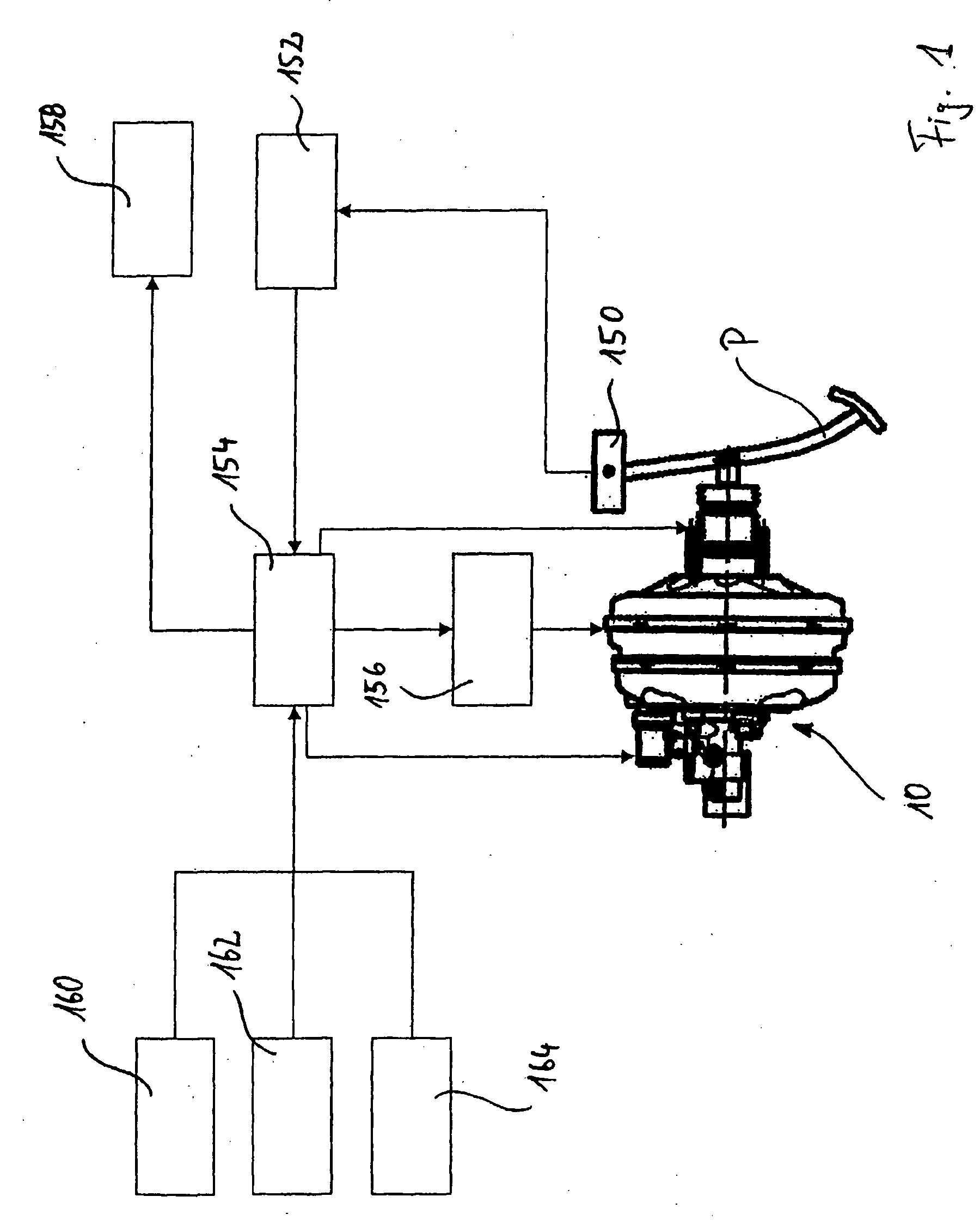
[0010] In order to be able to monitor the mode of operation of the brake force generator according to the invention and to provide a parameter for feedback of the response characteristic of the brake force generator according to the invention in a closed control loop, a development of the invention provides that the present position of the movable wall is detected by means of a position sensor. In said case, the position sensor may be of an inductive or mechanical design. A simple, economical and yet reliable development arises for example when the position sensor is designed with a feeler which rests under bias against the movable wall and may detect the position thereof in the event of a displacement.
[0013] As already mentioned above, unlike conventional brake boosters, the pedal actuating force in the solution according to the invention in a normal braking situation, i.e. in the fully functional state of the brake system, is not transmitted to the primary piston. Rather, it is necessary to generate an actuating force by means of the electromagnetic actuator. The actuator may therefore take the form of a linear drive or a rotary drive, the rotational movement of which is converted to a translatory movement by means a gear arrangement, for example a ball screw drive. A preferred embodiment of the invention provides that the electromagnetic actuator comprises a coil fastened to the control valve housing as well as a magnetic armature displaceable by means of the coil relative to the coil. With this constructional variant, it is possible to achieve an economical, exactly positionable brake force generator that operates reliably and with low friction.
[0021] In order upon actuation of the brake pedal to be able to convey to the driver a resistance response that is familiar from conventional brake systems, a development of the invention provides that the damper arrangement comprises a simulation spring, which is compressible by means of a force piston displaceable by means of the pedal counterforce hydraulic system, or / and fluid damping means, preferably a throttle, or / and a rubber-elastic stop washer. Whereas with the simulation spring and the rubber-elastic stop washer a progressive variation of force is achievable with increasing pedal actuation, the fluid damping means are used in particular to bring about a hysteresis that leads to a delayed return movement of the brake pedal after release thereof. The fluid damping means moreover have the effect that, given a sufficiently fast actuation of the brake pedal, they convey to the driver a resistance sensation familiar from conventional brake systems, namely in every operating situation of the brake system according to the invention.
[0022] As already explained above, the brake force generator is generally so designed that, even after the failure of individual components, it guarantees a reliable braking effect. Particularly when it is necessary to make the best possible use of the pedal actuating force exerted on the brake pedal by the driver in order to generate an actuating force in an emergency operating situation, the dissipation of some of the pedal actuating force owing to the action of the pedal counterforce simulating device is to be avoided. A development of the invention therefore provides that the pedal counterforce simulating device is cut in and cut out, as and when required. In particular, in this connection an embodiment of the invention provides that the hydraulic system of the pedal counterforce simulating device is designed with a controllable block valve, which in a first position, preferably in its passive position, uncouples the damper arrangement and the transmission piston arrangement hydraulically from one another and allows a substantially undamped movement of the transmission piston arrangement and which in a second position, preferably in its active position, connects the damper arrangement and the transmission piston arrangement hydraulically to one another. With regard to the control of the block valve, according to the invention it may be provided that the block valve at the start of a brake pedal actuation is switched from its passive position to its active position and is not returned from its active position to its passive position until after completion of the brake pedal actuation. Furthermore, the block valve may already be used to achieve a throttling effect in that it is provided with a throttle element, preferably with a spring-biased restrictor, which in the active position of the block valve throttles a hydraulic fluid flow to the damper arrangement. In this way, the hysteresis effect and the damping effect of the damper arrangement may be further intensified. Preferably, the restrictor is so disposed that, even when the block valve is switched to its passive position, it throttles a fluid flow in the hydraulic system so that the driver for example in an emergency operating situation, in which the damper arrangement is not connected to the brake pedal, senses a resistance upon an actuation of the brake pedal.

Problems solved by technology

However, the actuating force generating device used for this purpose in the context of the invention is not designed as a separate hydraulic system, which would lead to a considerable additional technical outlay and, in addition to the extra costs associated therewith, also to an increased susceptibility to faults.
This pressure difference subsequently leads to a displacement of the movable wall and hence to a displacement of the primary piston.

Method used


Image

  • Braking force generator for a hydraulic vehicle braking system
  • Braking force generator for a hydraulic vehicle braking system
  • Braking force generator for a hydraulic vehicle braking system

Examples


first embodiment

[0048] The pedal counterforce simulating device 106 is shown in FIG. 5 to an enlarged scale and in a sectional representation in a first embodiment, in which it is integrated in the cylinder housing 18. The connection channel 104 opens out into a hydraulic chamber 108, which is delimited by means of a simulation piston 110. The simulation piston 110 is displaceable along a longitudinal axis B inside the cylinder housing 18. The simulation piston 110 has a seating flange 112, against which one end of a simulation spring 114 rests. The simulation piston 110 further comprises a rounded-off extension 116, which projects into the simulation spring 114. The simulation spring 114 is disposed in a spring chamber 118, which is closed by a closure plug 120 secured by means of a fastening ring 122. The closure plug 120 has a central opening 128. The spring chamber 118 is moreover connected by a lateral bore 126 to the atmosphere. Disposed in the closure plug 120 is a rubber-elastic stop washer...

second embodiment

[0065] The following is a brief description of FIG. 6. FIG. 6 shows the pedal counterforce simulating device. To facilitate the description and avoid repetition, for components of an identical type or function the same reference characters as in the description of FIG. 5 are used, but with the letter “a” appended.

[0066] The embodiment according to FIG. 6 differs from the embodiment according to FIG. 5 only in that the hydraulic chamber 108a, the simulation piston 110a, the simulation spring 114a, the rubber-elastic stop washer 124a and the closure plug 120a are disposed in a separate housing 168a and designed as a preassembled module, wherein the housing 168a is screwed by means of a threaded connection piece 170a tightly into a corresponding location opening 172a of the housing 18a.

[0067]FIG. 8 shows a further embodiment of the brake force generator according to the invention. To avoid repetition, once again only the differences from the embodiments according to FIGS. 3 and 4 are ...


PUM


Abstract

In a brake force generator for a vehicle hydraulic brake system having a force input element, which is connectable or connected to a brake pedal and displaceable in a base housing of the brake force generator, a master cylinder, in which a primary piston is displaceably guided for generating a hydraulic brake pressure, a pedal counterforce simulating device connected to the force input element, a pedal actuation detecting device for detecting a pedal actuation, and an actuating force generating device for exerting an actuating force on the primary piston, it is provided that the actuating force generating device comprises a control valve, a chamber arrangement and an electromagnetic actuator, wherein the chamber arrangement is designed with a vacuum chamber and a working chamber, which is separated from the vacuum chamber by a movable wall and is fluidically connectable to the vacuum chamber by the control valve, and wherein the control valve may be activated in accordance with the detected pedal actuation.

Description

CROSS-REFERENCE TO RELATED APPLICATIONS [0001] This application is a continuation of International Application No. PCT / EP2005 / 000538 filed Jan. 20, 2005, the disclosures of which are incorporated herein by reference, and which claimed priority to German Patent Application No. 10 2004 005 107.0 filed Feb. 2, 2004 and German Patent Application No. 20 2004 009 835.0 filed Jun. 23, 2004, the disclosures of which are incorporated herein by reference. BACKGROUND OF THE INVENTION [0002] The present invention relates to a brake force generator having a force input element, which is connectable or connected to a brake pedal and displaceable in a base housing of the brake force generator, a master cylinder, in which a primary piston is displaceably guided, wherein the primary piston with the master cylinder delimits a primary pressure chamber for generating a hydraulic brake pressure, a pedal counterforce simulating device connectable to the force input element, a pedal actuation detecting de...

Claims


Application Information

Patent Timeline
Patent Type & Authority Applications(United States)
IPC IPC(8): B60T8/44B60T7/04B60T8/32B60T8/40B60T13/563B60T13/57B60T13/72B60T17/18
CPCB60T7/042B60T8/4077B60T17/18B60T13/57B60T13/563B60T8/00B60T8/40B60T13/52
Inventor SCHLUTER, PETER
Owner LUCAS AUTOMOTIVE GMBH
Why Eureka
Try Eureka