Electro-optical arrangement

a technology of optical arrangement and optical arrangement, applied in the direction of instruments, static indicating devices, etc., can solve the problems of slow color change, electric current is needed to maintain the colored state, and it is difficult to obtain strong color change or bright colors, etc., to achieve the effect of saving tim

Inactive Publication Date: 2007-01-04
SEIKO EPSON CORP +1
View PDF9 Cites 101 Cited by
  • Summary
  • Abstract
  • Description
  • Claims
  • Application Information

AI Technical Summary

Benefits of technology

[0018] The driver stage may be configured such that, while the latched drive signals (Vdata) are being applied to one row of the array, the drive signals

Problems solved by technology

This type of ECD, however, is slow to change color due to the low migration rate of the counter-ions in the bulk polymer.
It is also difficult to obtain strong color changes or bright colors.
It has the drawback, however, that an electric current is needed to maintain the colored state, because the two types of colored molecules diffuse through the system and react with each other to restore the bleached (clear) states.
Consequently it cannot be used for large-area devices or for battery-powered displays, sin

Method used


Image

  • Electro-optical arrangement
  • Electro-optical arrangement
  • Electro-optical arrangement

Examples


Embodiment Construction

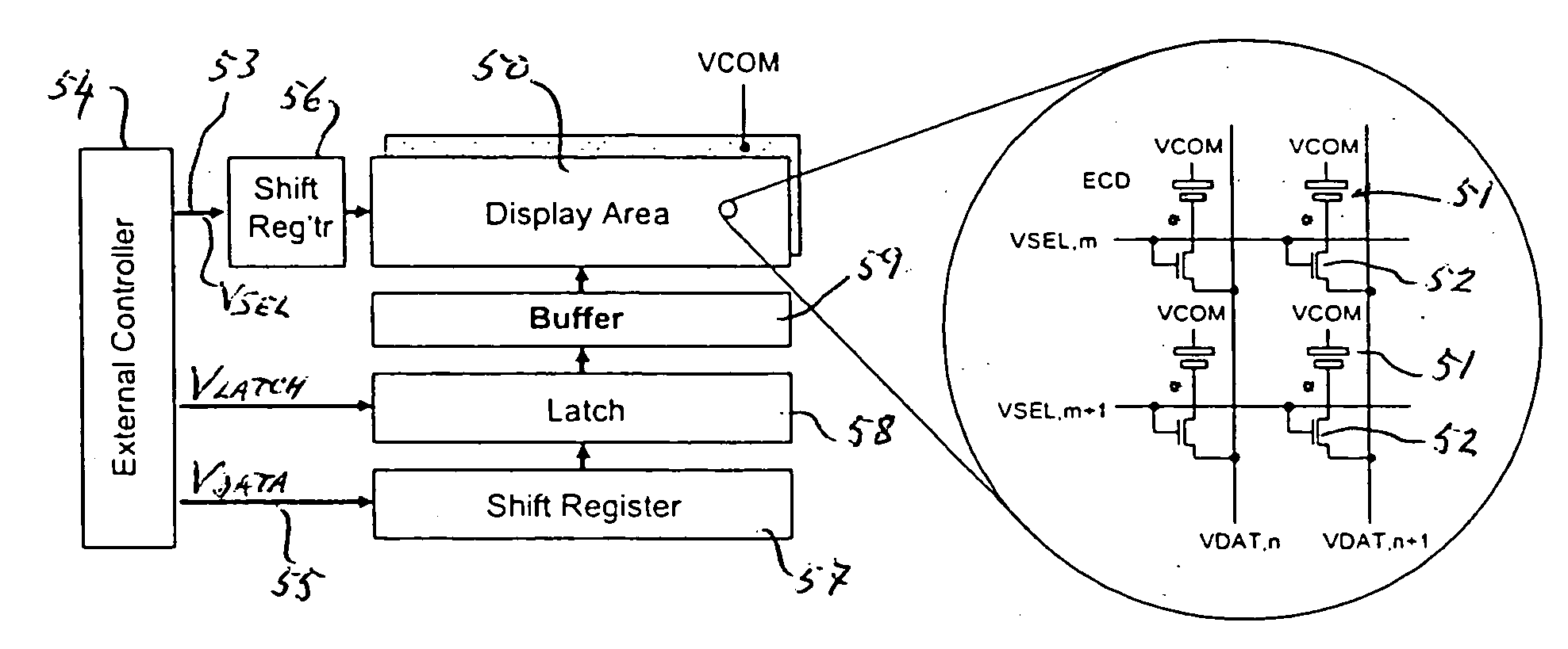
[0041] An embodiment of an electro-optical arrangement in accordance with the invention is shown in FIG. 5. In FIG. 5 the display area 50 comprises an active-matrix electrochromic display driving scheme using low-temperature polysilicon thin-film transistor technology (LTPS-TFT).

[0042] The electrochromic pixel elements 51 are connected such that all working electrodes are connected to individual select transistors 52. The working electrodes are shown by the shorter rectangular box, which indicates negative polarity. These electrodes are responsible for the coloration that occurs when the pixel elements are driven into their light-modulated, as opposed to cleared (transparent), state.

[0043] The display area 50 is driven by line-select signals (Vsel) 53 provided by an external controller 54 and by data signals (Vdata) 55 likewise provided by the external controller 54. The line-select signals (Vsel) and data signals (Vdata) are fed into respective shift registers 56, 57 and the para...


PUM


Abstract

An electro-optical arrangement includes an electrochromic device which can take either a cleared (transparent) state, a first display state or a second display state, and a driving stage which provides first and second electrode-drive signals to drive the first and second electrodes of the device. At least one of the electrode-drive signals is supplied by way of a polysilicon thin-film buffer. The driving stage in an initial clearing operation outputs approximately equal voltages to the electrodes, which places the device into its transparent state. Subsequently the driver stage applies voltages to the electrodes, such that the device assumes either the first display state or the second display state. In either state it is arranged for the device not to be subjected to more than a safe operating voltage. Preferably, in one of the electrochromic device's two display states one of its electrodes is supplied with a voltage which is higher than the voltage (Vcom) on the other electrode, while in the other of its two display states the one electrode is supplied with a voltage which is lower than the voltage (Vcom) on the other electrode, the two voltage differences being less than the safe operating voltage. The second display state may itself be a transparent state, while the first display state may be a colored state. Alternatively, the two states may be differently colored states.

Description

TECHNICAL FIELD [0001] The invention relates to an electro-optical arrangement including an electrochromic device. The invention in a second aspect thereof also relates to a method of driving an electrochromic device. BACKGROUND ART [0002] Electrochromic devices (ECDs) are known, which undergo a reversible color change of a material when an electric current or voltage is applied to the device. This phenomenon is known as electrochromism. A typical ECD consists of two conductors sandwiching a combination of an electrochromic material and an electrolyte. [0003] There are three types of ECD: the intercalation type, the solution-based type and the nanostructure type. The principle of the intercalation type is shown in FIG. 1(a). The electrodes take the form of transparent electrodes 12, 13 on respective glass substrates 10, 11, the electrodes being covered with an organic or inorganic polymer 14, 15. The two materials normally display complementary electrochromism and hence produce the ...

Claims


Application Information

Patent Timeline
IPC IPC(8): G09G3/38
CPCG09G3/2022G09G3/38G09G2300/08G09G2330/022G09G2310/027G09G2310/0272G09G2310/06G09G2310/0245
Inventor TAM, SIMON
Owner SEIKO EPSON CORP
Why Eureka
Try Eureka