

Method for manufacturing projection optical system and projection optical system
a technology of optical system and manufacturing method, which is applied in the direction of optics, projectors, instruments, etc., can solve the problems of not necessarily easy to achieve desired optical performance, require a relatively long time, and shorten the time necessary so as to simplify the structure of the projection optical system, the effect of reducing the time required for adjusting the projection optical system
- Summary
- Abstract
- Description
- Claims
- Application Information
AI Technical Summary
Benefits of technology
Problems solved by technology
Method used
Image

Examples
first embodiment
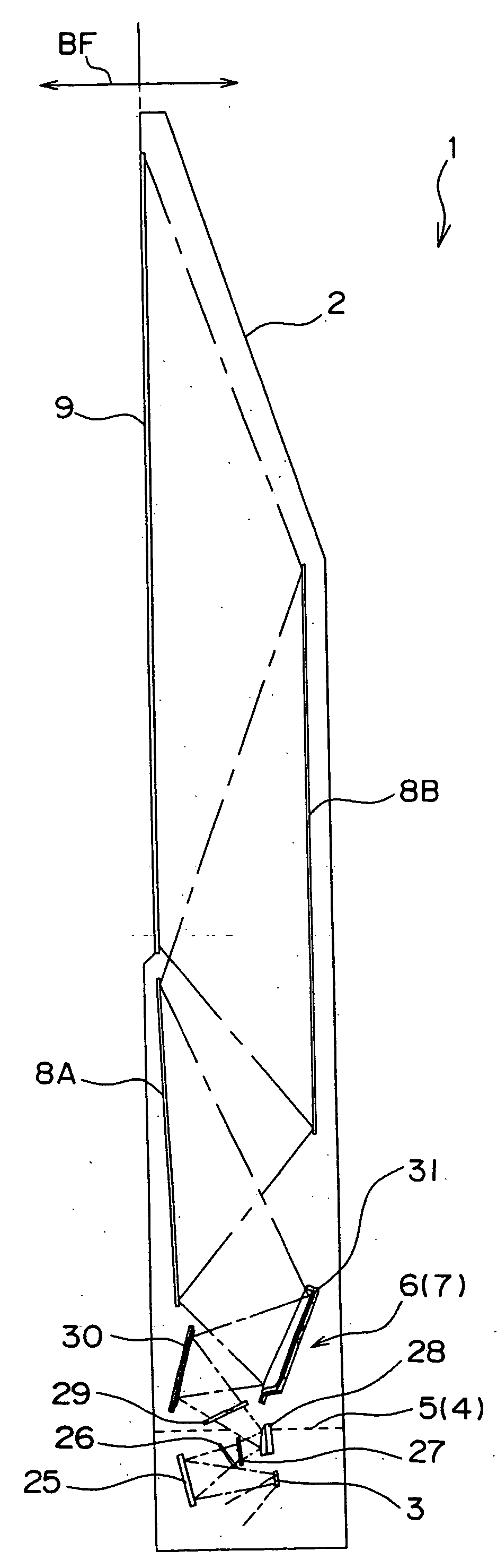
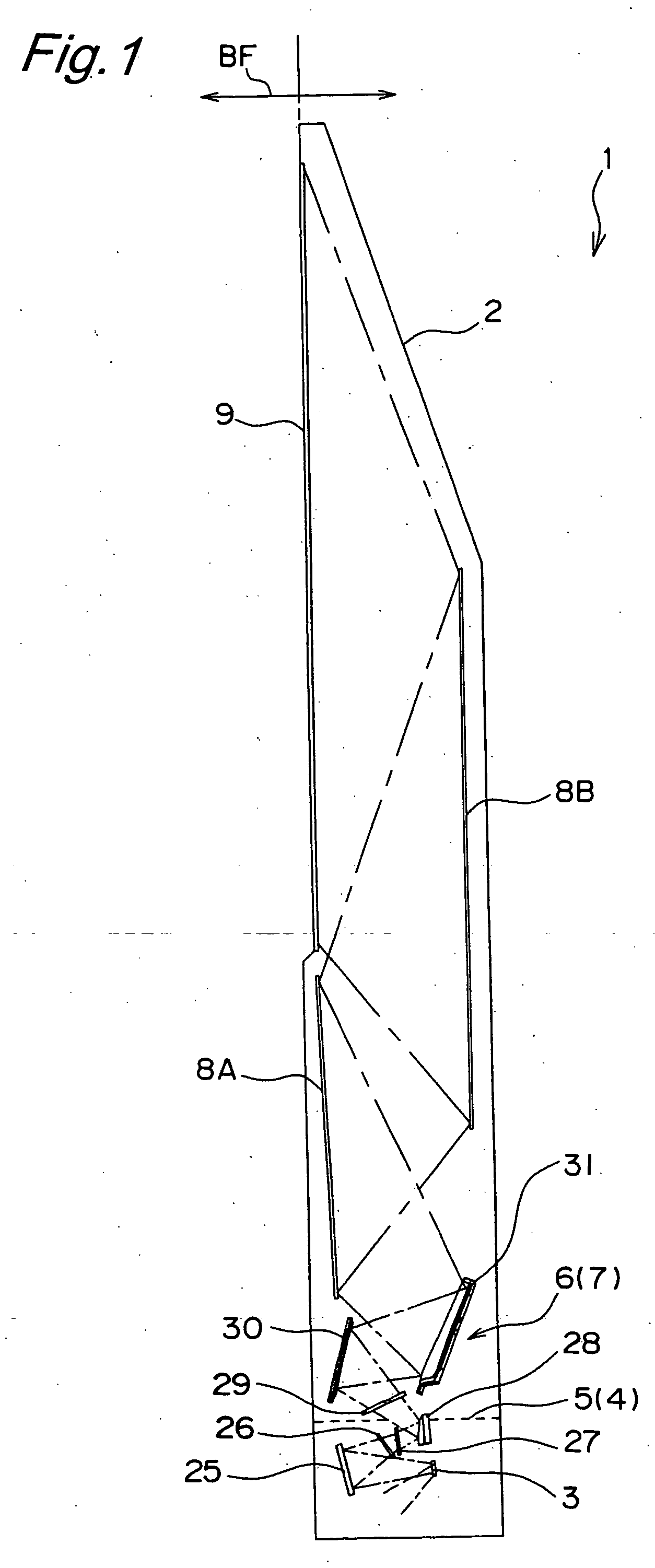
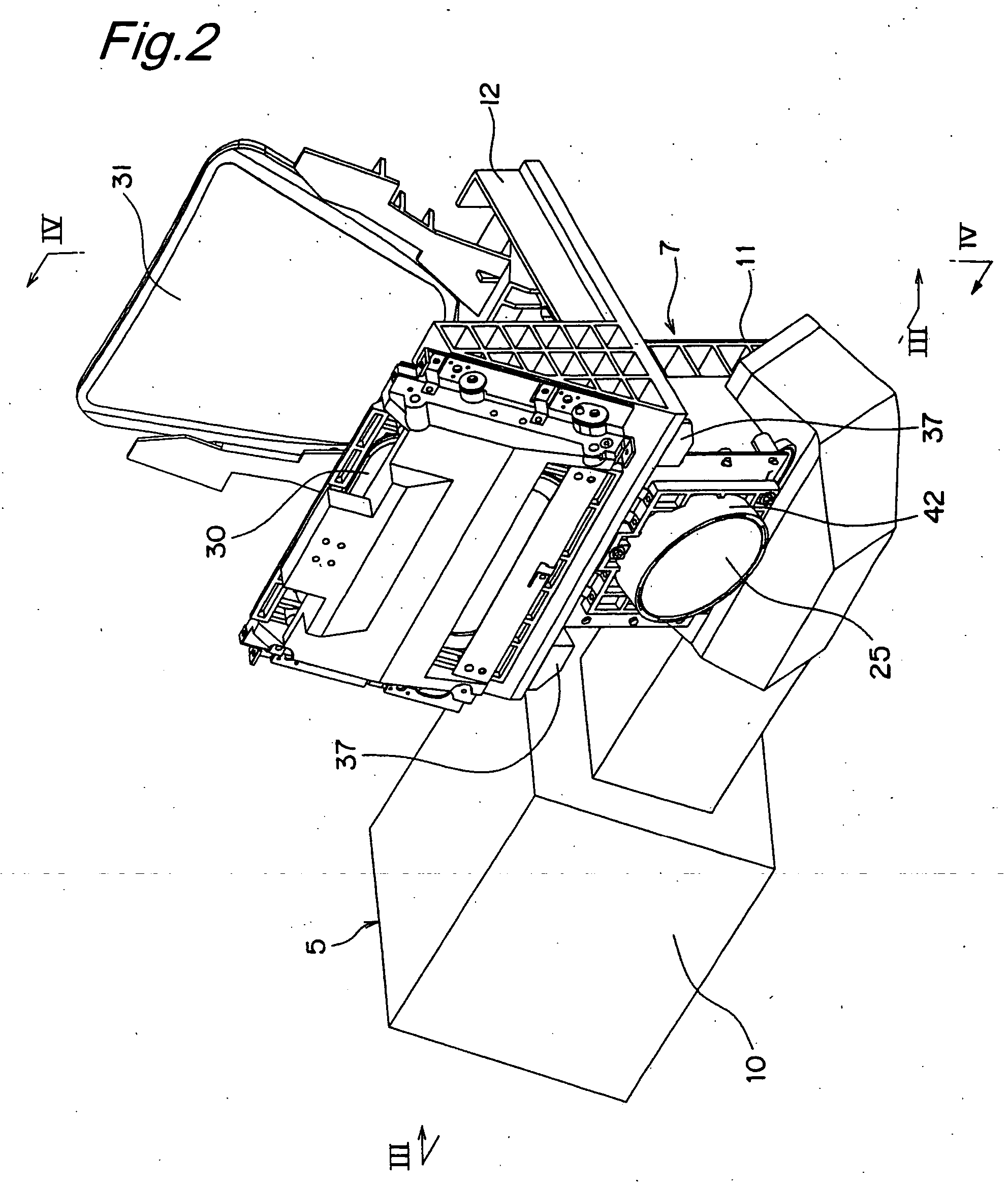
[0061]FIG. 1 shows a rear projection television (rear projection TV) 1 which is an embodiment of a projection-type image display apparatus of the present invention. Accommodated within the casing 2 of the rear projection TV 1 are a digital micromirror device (DMD) 3 which is one example of a reflection-type image formation device, an illumination optical system unit 5 having an illumination optical system 4 which irradiates the DMD 3 with illumination light, and a projection optical system unit 7 having a projection optical system 6 which enlarges and projects projection light reflected by the DMD 3, i.e., image light. Arranged on an upper front of the casing 2 is positioned a screen 9, onto which the image enlarged by the projection optical system 6 is projected through two planar mirrors 8A and 8B. Further referring to FIG. 2, in addition to a housing 10 of the illumination optical system unit 5, the casing 2, at a bottom portion, accommodates a lower pedestal component 11 and an ...
second embodiment
[0095] An projection optical system 6 of a rear projection TV 1 that can be manufacture by a manufacturing method for a projection optical system according to a second embodiment of the present invention is different from the first embodiment in the following points. First, a DMD 3 is fixed onto the image forming holding plate 38 in such a way that the DMD 3 does not translated in the X axis, Y axis and Z axis directions nor rotate around the X axis, the Y axis and the Z axis. In other words, there is no mechanism to adjust the position and the inclination of the DMD 3. Moreover, the mirror holding component 45 of a convex mirror 28 is mounted on a lower pedestal component 11 in such a way that the mirror holding component 45 can be translated in the Y axis and Z axis. In other words, the position of the convex mirror 28 is adjustable in the Y axis and Z axis directions. Further, the concave mirror 25 can be translated along the X axis, Y axis and Z axis directions as described here...
third embodiment
[0108] In the projection optical system 6 in the first and second embodiments, an optical path length adjustment mechanism 300 as shown in FIGS. 17A and 17B may be placed between the DMD 3 and the concave mirror 25. The optical path length adjustment mechanism 300 has wedge-type optical elements 301 and 302 which respectively have inclined surfaces 301a and 302a inclined with respect to the normal direction of an image formation surface of the DMD 3 (X axis direction of the DMD 3) and which are made of a material with high translucency. The position and the inclination of one wedge-type optical element 301 are fixed. The other wedge-type optical element 302 can be moved backward from and forward to the wedge-type optical element 301 in the Y axis direction by a screw-type position adjustment mechanism 303 (see arrows A1 and A2 in FIG. 17B). Regardless of the position of the wedge-type optical element 302, the inclined surfaces 301a and 302a of the two wedge-type optical elements 301...
PUM
 Abstract
Description
Claims
Application Information