Light source driving method and projector

a driving method and light source technology, applied in the field of light source driving method and projector, can solve the problems of flicker generation and unstable discharge location, and achieve the effects of avoiding brightness instability, reducing the judgment of brightness difference, and increasing and decreasing brightness differen

Inactive Publication Date: 2007-01-04
COLUMBIA PEAK VENTURES LLC
View PDF9 Cites 10 Cited by
  • Summary
  • Abstract
  • Description
  • Claims
  • Application Information

AI Technical Summary

Benefits of technology

[0005] To avoid this unstableness of brightness, a method for photographing plural video images in a stopping state of a focus lens and calculating an average value is also considered and executed. However, it takes time until the focusing lens is focused, and the focus lens might be focused for a shorter time by a manual focus adjustment.
[0006] Further, the unstableness of brightness of the image data is considered and an increase and decrease judgment of the brightness difference may be also sequentially made while moving the focus lens. However, focus accuracy is greatly reduced. W

Problems solved by technology

However, when the discharge of electrons between electrodes of the lamp is continued for a long

Method used


Image

  • Light source driving method and projector
  • Light source driving method and projector
  • Light source driving method and projector

Examples


modified example 1

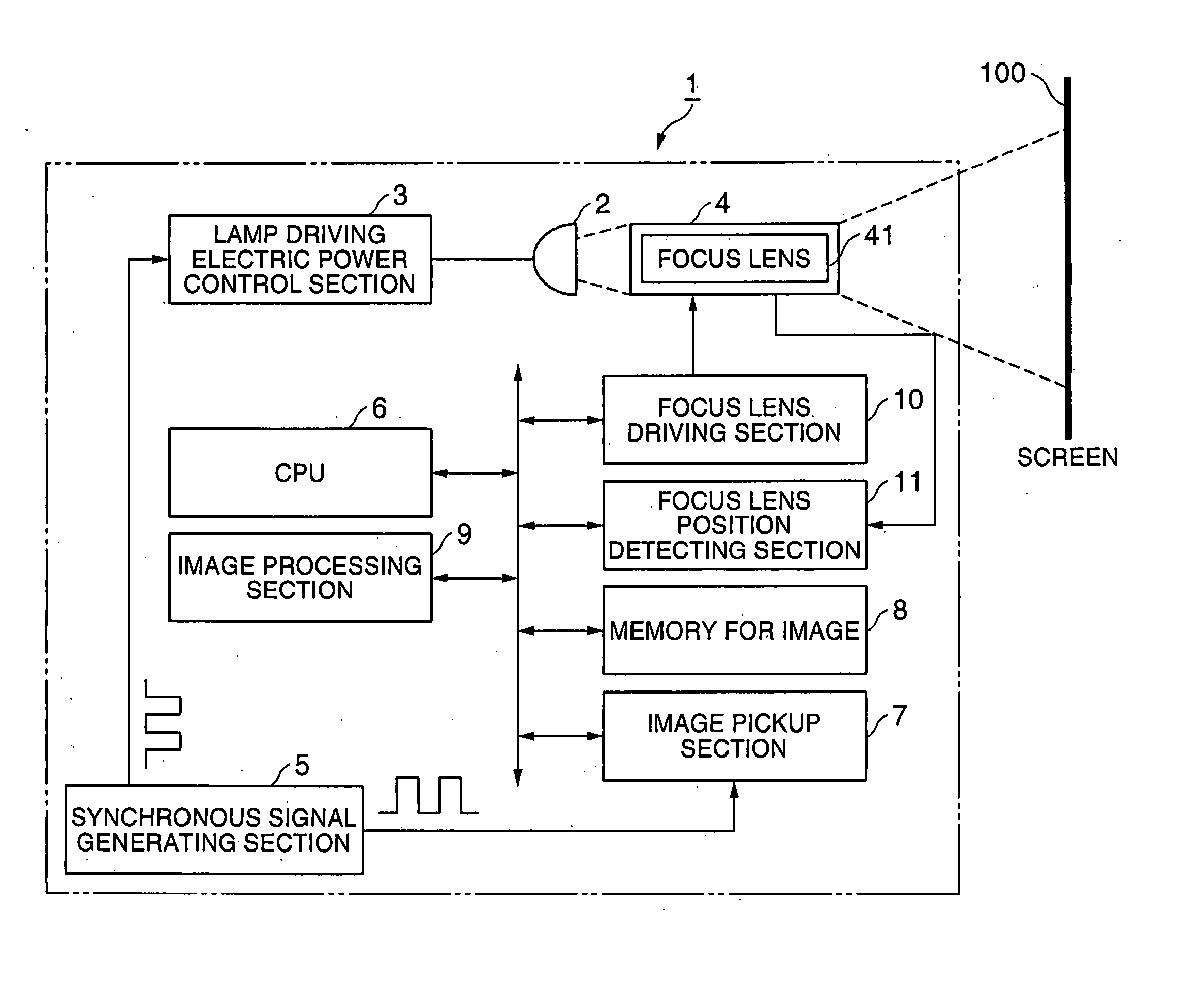
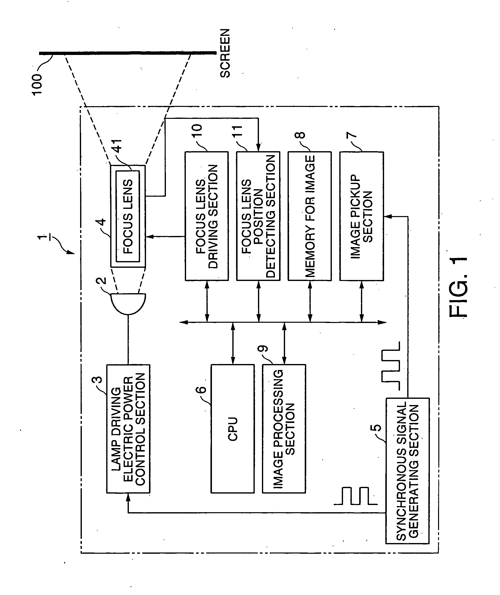
[0064] In the above embodiment mode, the reference signal of the lamp driving electric power control section 3 is set by using the projector 1 and the clock generator as a reference signal of the image pickup section 7 constituting the projector 1. However, the synchronous signal generating section may be also constructed by using the clock generator arranged in the lamp driving electric power control section 3 to set the reference signal of the image pickup section 7.

modified example 2

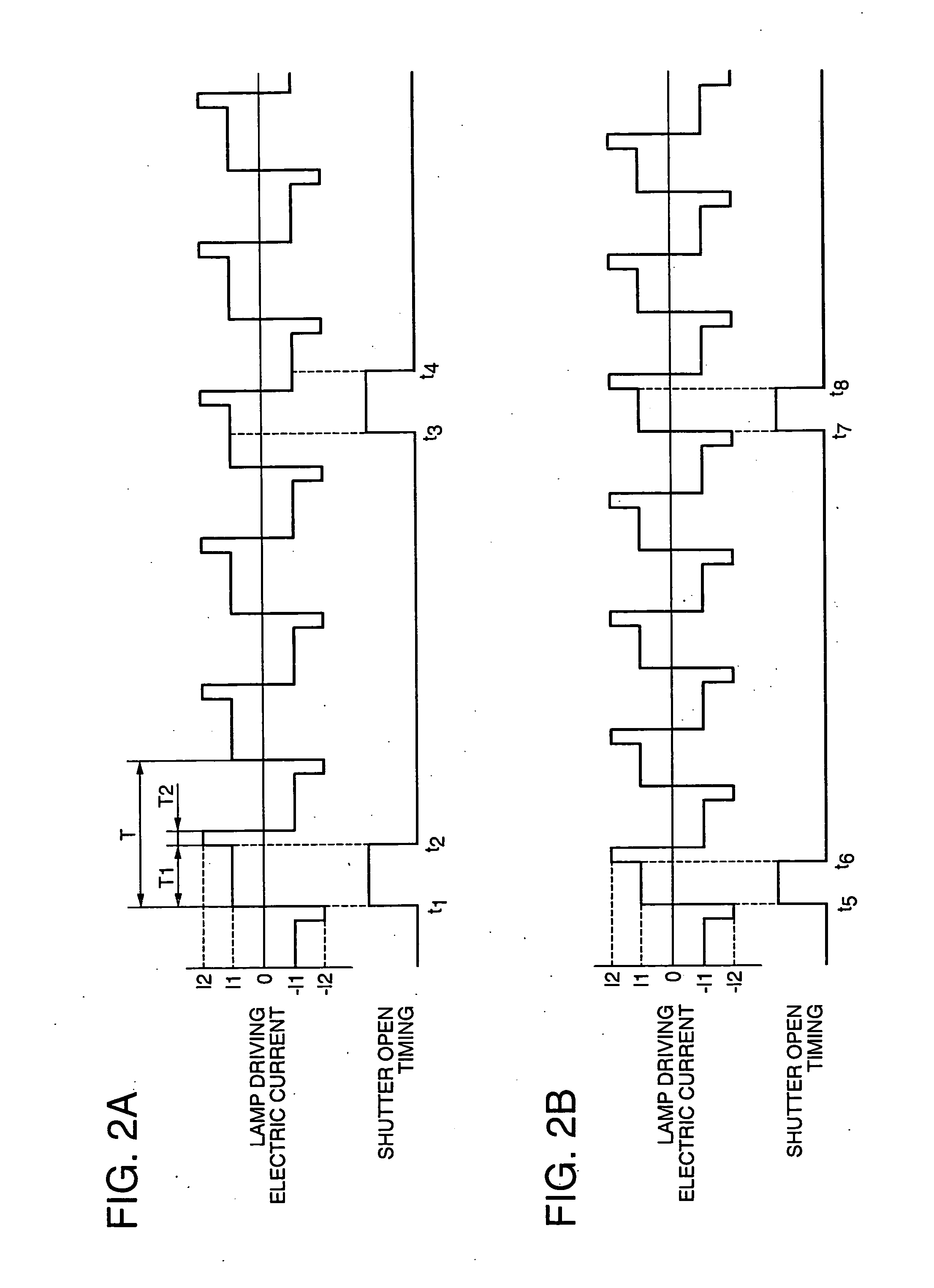
[0065] In the above embodiment mode, the explanation is made by using the driving waveform provided by adding the high electric current I2 for stabilizing the discharge locus between the electrodes of the lamp 2 and preventing the flicker of the projected image. However, the present invention can be also applied to a case in which only the driving waveform of the electric current I1 is used without adding the high electric current I2. In this case, the auto focus adjustment also considering the influence of brightness, etc. on the image data due to the change of polarities of the output electric current is made by synchronizing the shutter open time of the image pickup section 7 and the lamp driving electric current waveform of the lamp driving electric power control section 3. Accordingly, a further accurate adjustment can be made with respect to the auto focus adjustment in the driving waveform provided by an alternating electric current using only the electric current I1.

modified example 3

[0066] In the above embodiment mode, the electric current is changed to the uniform high electric current I2 while the light source is lighted after the image data for the auto focus adjustment are obtained. However, the present invention is not limited to this case, but the electric current may be also changed to an un-uniform electric current value. In this case, the changed electric current value can be set by confirming the influence of the electric current value with respect to the specification and performance of the light source, the performance of another optical system and the quality of the projected image, etc.


PUM


Abstract

An object of the invention is to provide a light source driving method for supplying electric power to a light source of a projector, and and to provide a projector using this light source driving method. The projector has a lamp (2) as a light source for emitting light, a lamp driving electric power control section (3) as a light source driving section for supplying electric power for operating the lamp (2), an image pickup section (7) as an image obtaining section for receiving a projected image and obtaining image data to adjust the projected image, and a synchronous signal generating section (5) for generating a signal as an operation reference. The synchronous signal generating section (5) generates a first operation signal for determining operation timing of an electric current output of the lamp driving electric power control section (3), and a second operation signal for determining operation timing for receiving the projected image and obtaining the image data by the image pickup section (7), and the lamp driving electric power control section (3) and the image pickup section (7) are synchronously operated.

Description

TECHNICAL FIELD [0001] The present invention relates to a light source driving method for supplying electric power to a light source of a projector, and the projector using this light source driving method. BACKGROUND ART [0002] The light source of the projector generally emits light of high brightness by using a lamp of a discharge system. However, when the discharge of electrons between electrodes of the lamp is continued for a long time, a locus of the discharge becomes unstable and a flicker is generated in a projected image. Therefore, there is a light source driving device having a function for stabilizing the locus of the discharge and preventing the flicker by performing an operation for periodically supplying a normal electric current and a large electric current in comparison with the normal electric current on the side of the light source driving device for supplying electric power to the lamp and lighting (operating) the lamp (see patent literature 1 (FIG. 4)). Otherwise...

Claims


Application Information

Patent Timeline
IPC IPC(8): G03B21/20
CPCH04N9/3155H04N5/74G03B21/14H05B41/38G03B21/00
Inventor MATSUMOTOFURUI, SHIKI
Owner COLUMBIA PEAK VENTURES LLC
Why Eureka
Try Eureka