Entangled-photons range finding system and method

Inactive Publication Date: 2007-01-04
MDA INFORMATION SYST
View PDF41 Cites 16 Cited by
  • Summary
  • Abstract
  • Description
  • Claims
  • Application Information

AI Technical Summary

Benefits of technology

[0011] Known distance-determination techniques, such as RADAR and LIDAR, generally rely on transmitting certain types of electromagnetic radiation (e.g., relatively narrow band electromagnetic radiation, coherent electromagnetic radiation, pulsed electromagnetic radiation) that reflects off of an object in order to determine its distance from the RADAR or LIDAR unit. Howeve

Problems solved by technology

Thus, detectability by third parties remains a major drawback of using RADAR and

Method used


Image

  • Entangled-photons range finding system and method
  • Entangled-photons range finding system and method
  • Entangled-photons range finding system and method

Examples


Example

[0038] The particulars shown herein are by way of example and for purposes of illustrative discussion of the exemplary embodiments of the present invention only and are presented in the cause of providing what is believed to be the most useful and readily understood description of the principles and conceptual aspects of the present invention. In this regard, the description taken with the drawings provides a fundamental understanding of the present invention, making apparent to those skilled in the art how the several forms of the present invention may be embodied in practice.

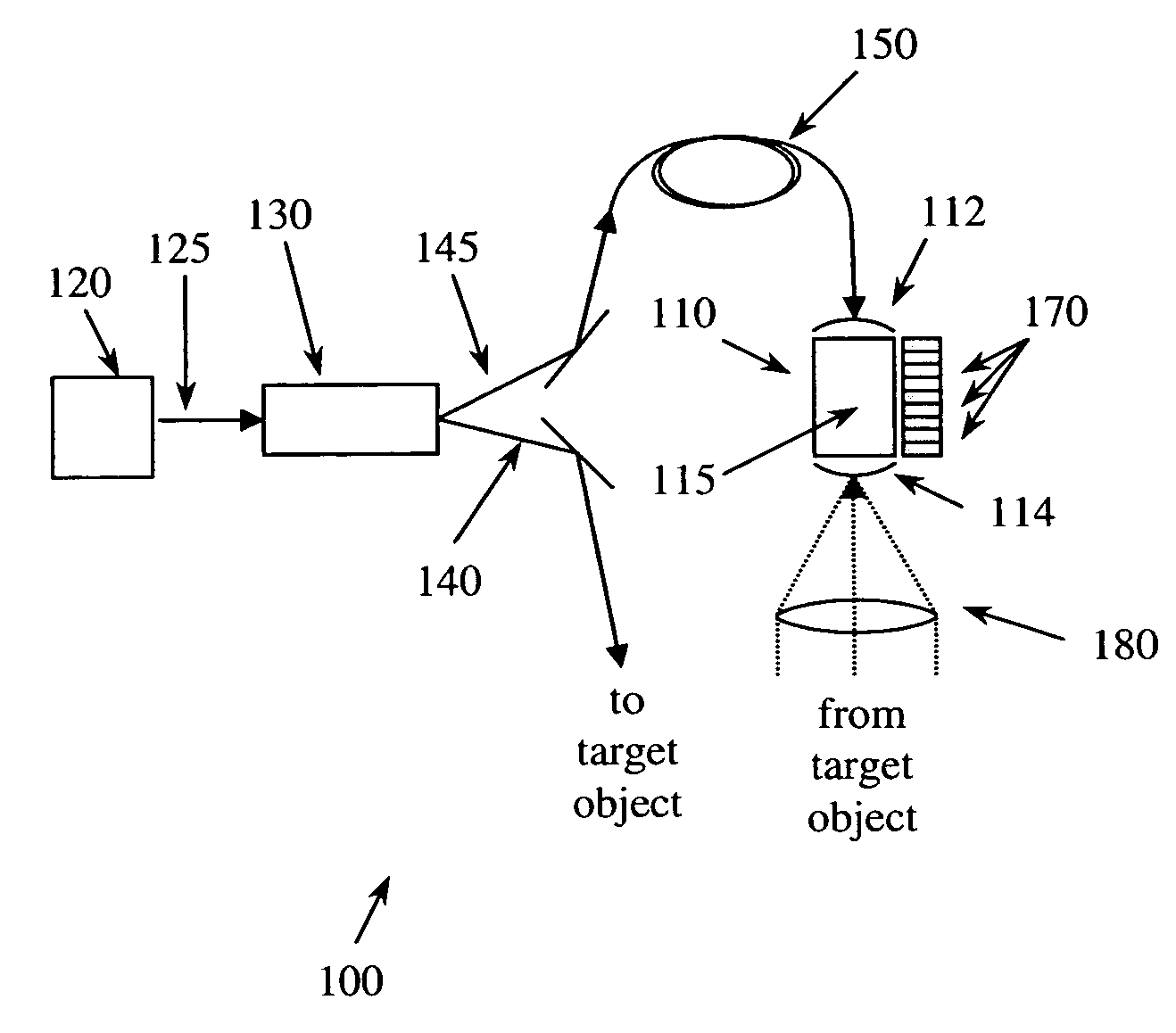
[0039]FIG. 1 depicts an embodiment of an entangled-photon range finder 100. Entangled-photon range finder 100 includes a coherent light source 120 (e.g., a laser), which provides pump beam 125. Pump beam 125 is directed to nonlinear crystal 130 (e.g., beta barium borate), which type-II parametrically down converts the photons of pump beam 125 into entangled-photon pairs that are separated (e.g., using a polar...


PUM


Abstract

A method of determining a distance to an object is presented. A first photon and a second photon are simultaneously generated. The first photon is reflected off an object. The second photon is directed to an optical cavity. An arrival of the first photon is correlated with an arrival of the second photon, and the distance to the object is at least partially determined using the correlation.

Description

CROSS-REFERENCE TO RELATED APPLICATIONS [0001] The present application claims priority to U.S. Utility patent application Ser. No. 10 / 850,394, to Kastella et al., entitled “System and Method of Detecting Entangled Photons,” filed on May 21, 2004, and benefit of U.S. Provisional Patent Application No. 60 / 555,699, to Zaugg, entitled “Entangled-Photon Range Finding System and Method,” filed on Mar. 24, 2004, the disclosures of which are expressly incorporated by reference herein in their entireties.GOVERNMENT INTERESTS [0002] To the extent that this invention was made with Government support under contract number NRO-02-C-0371, awarded by the National Reconnaissance Office, the Government has certain rights in this invention.BACKGROUND OF THE INVENTION [0003] 1. Field of the Invention [0004] The invention relates to determining distances. In particular, the invention relates to using one photon of a pair of entangled photons, reflected off an object, to determine a distance to that obj...

Claims


Application Information

Patent Timeline
IPC IPC(8): G01C3/08G02F1/01H01J40/14
CPCG01C3/08G01S17/08
Inventor ZAUGG, THOMAS
Owner MDA INFORMATION SYST
Why Eureka
Try Eureka