Technique for forming nickel silicide by depositing nickel from a gaseous precursor

a technology of gaseous precursors and nickel silicides, which is applied in the direction of solid-state diffusion coatings, coatings, transistors, etc., can solve the problems of reducing the cross-sectional area of these lines and regions, increasing the electric resistance of conductive lines and contact regions, and increasing the difficulty of forming

Active Publication Date: 2007-01-04
ADVANCED MICRO DEVICES INC
View PDF4 Cites 29 Cited by
  • Summary
  • Abstract
  • Description
  • Claims
  • Application Information

AI Technical Summary

Benefits of technology

[0022] In accordance with yet another illustrative embodiment of the present invention, a deposition system comprises a reactor configured to supply gaseous nickel tetra carbonyl, a process chamber, which is in fluid connection with the reactor, and a substrate holder that is located within the process chamber and that is configured to receive and hol...

Problems solved by technology

Shrinking the feature sizes, however, creates certain problems that may partially offset the advantages obtained by reducing the feature sizes.
However, upon decreasing the channel length of the transistor elements, the electrical resistance of conductive lines and contact regions, i.e., of regions that provide electrical contact to the periphery of the transistor elements, becomes a major issue since the cross-sectional area of these lines and regions is also reduced.
Moreover, a higher number of circuit elements per units area also requires an increased number of interconnections between these circuit elements, wherein commonly the number of required interconnects increases in a non-linear manner with the number of circuit elements so that the available real estate for interconnects becomes even more limited.
Although reducing the feature size of a transistor element improves device performance due to the reduced channel length, the shrinkage of the gate ele...

Method used


Image

  • Technique for forming nickel silicide by depositing nickel from a gaseous precursor
  • Technique for forming nickel silicide by depositing nickel from a gaseous precursor
  • Technique for forming nickel silicide by depositing nickel from a gaseous precursor

Examples


Embodiment Construction

[0028] Illustrative embodiments of the invention are described below. In the interest of clarity, not all features of an actual implementation are described in this specification. It will of course be appreciated that in the development of any such actual embodiment, numerous implementation-specific decisions must be made to achieve the developers' specific goals, such as compliance with system-related and business-related constraints, which will vary from one implementation to another. Moreover, it will be appreciated that such a development effort might be complex and time-consuming, but would nevertheless be a routine undertaking for those of ordinary skill in the art having the benefit of this disclosure.

[0029] The present invention will now be described with reference to the attached figures. Various structures, systems and devices are schematically depicted in the drawings for purposes of explanation only and so as to not obscure the present invention with details that are we...


PUM

PropertyMeasurementUnit
Temperatureaaaaaaaaaa
Thicknessaaaaaaaaaa

Abstract

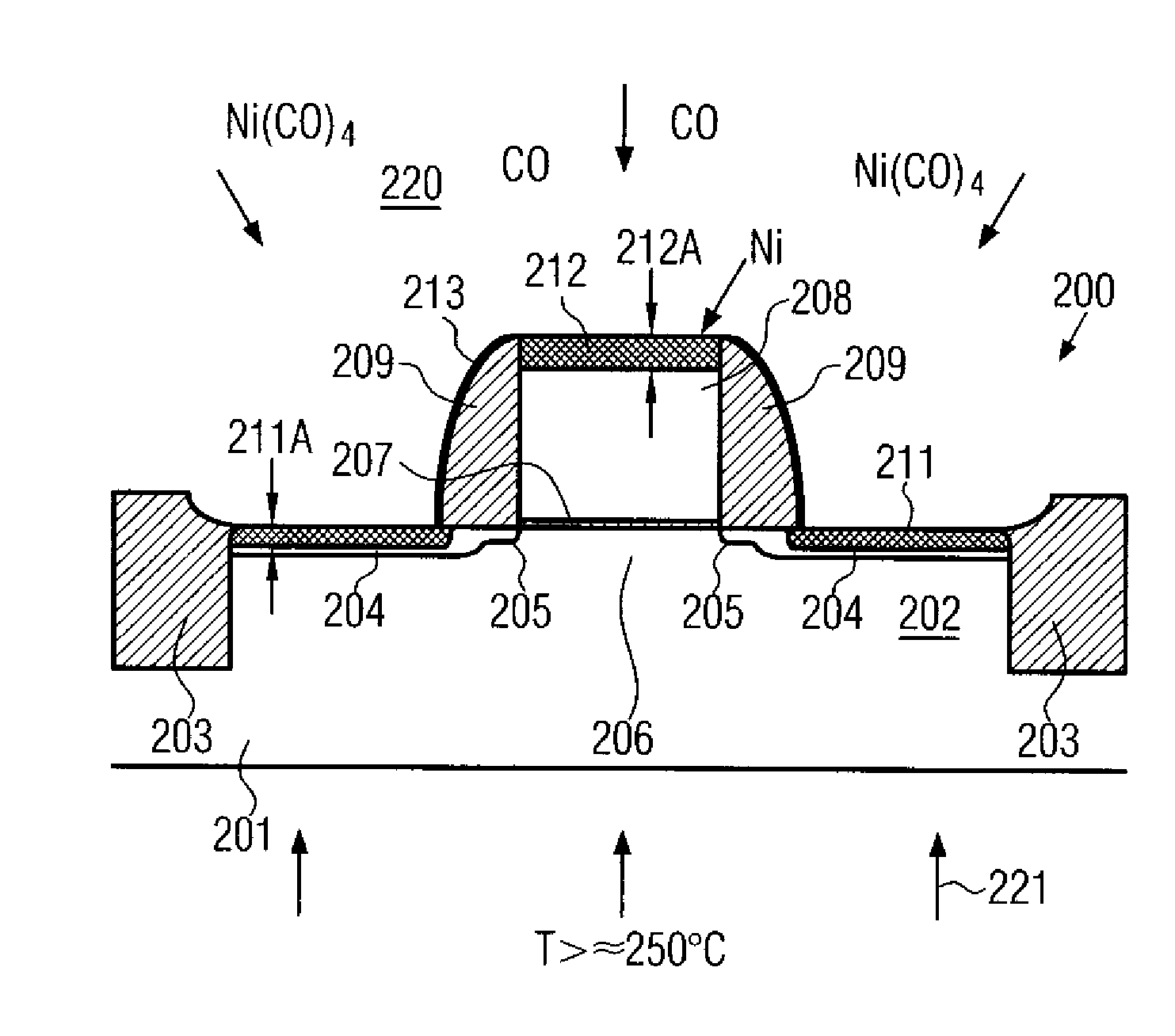
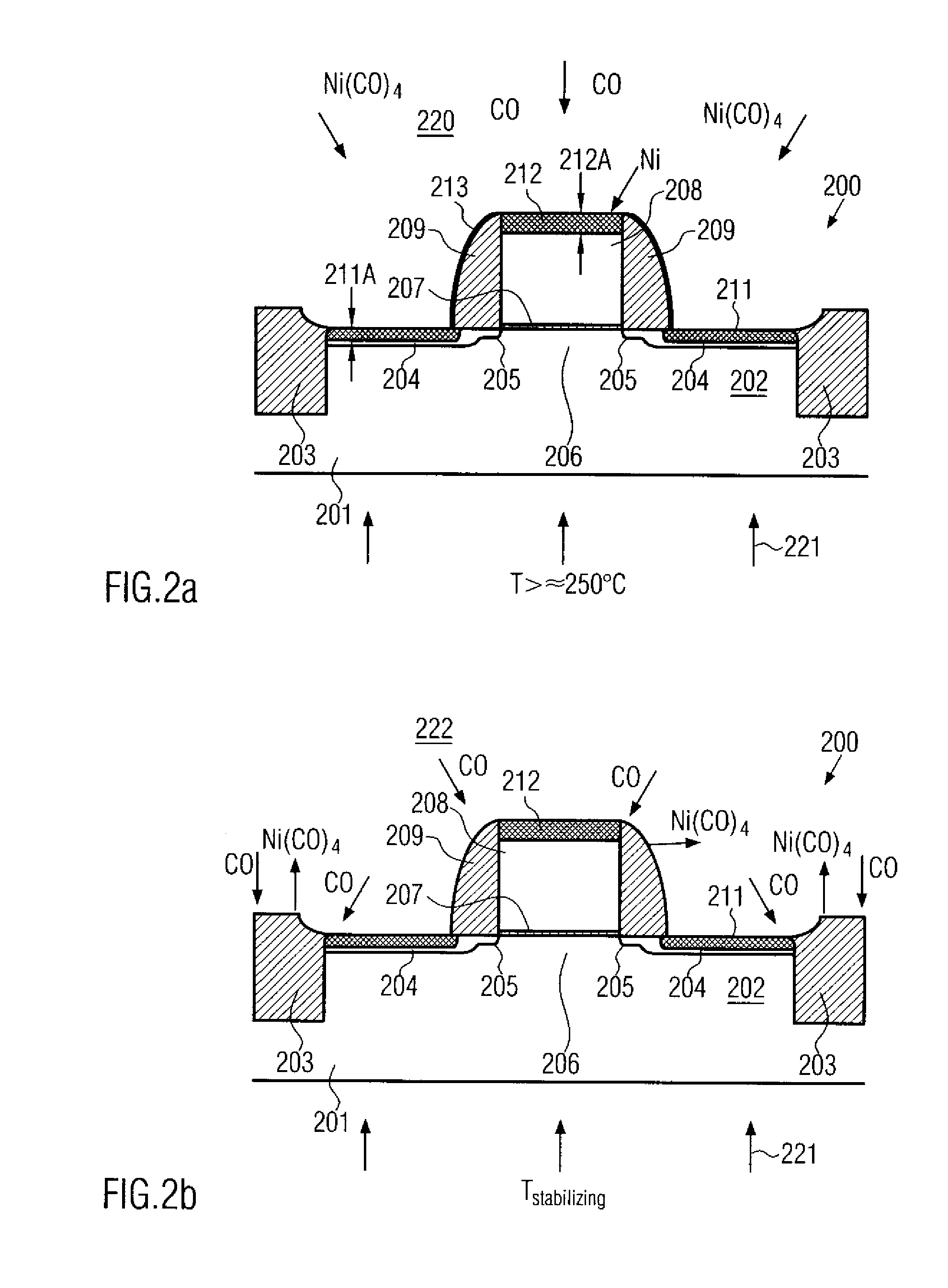
Nickel silicide is formed on the basis of a gaseous precursor, such as nickel tetra carbonyl, wherein the equilibrium of the decomposition of this gas may be controlled to obtain a highly selective nickel silicide formation rate. Moreover, any etch step for removing excess nickel may be avoided, since only minute amounts of nickel may form on exposed surfaces, which may then be effectively removed by correspondingly shifting the equilibrium. Consequently, reduced process complexity, enhanced controllability and enhanced tool lifetime may be obtained.

Description

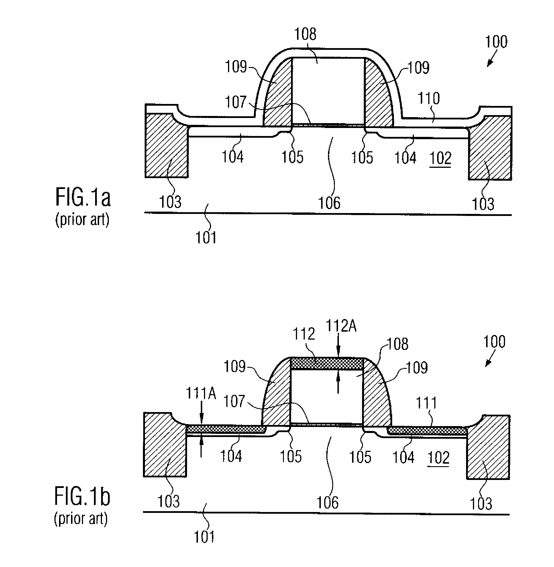
BACKGROUND OF THE INVENTION [0001] 1. Field of the Invention [0002] Generally, the present invention relates to the fabrication of integrated circuits, and, more particularly, to the formation of nickel silicide regions on silicon-containing conductive circuit elements to decrease a sheet resistance thereof. [0003] 2. Description of the Related Art [0004] In modem ultra-high density integrated circuits, device features are steadily decreasing to enhance device performance and functionality of the circuit. Shrinking the feature sizes, however, creates certain problems that may partially offset the advantages obtained by reducing the feature sizes. Generally, reducing the size of, for example, a transistor element such as a MOS transistor, may lead to superior performance characteristics due to a decreased channel length of the transistor element, resulting in a higher drive current capability and enhanced switching speed. However, upon decreasing the channel length of the transistor ...

Claims


Application Information

Patent Timeline
IPC IPC(8): H01L21/44C23C16/16
CPCC23C10/04C23C16/16C23C26/00H01L21/28052H01L29/6659H01L21/28562H01L29/4933H01L29/665H01L21/28518
Inventor STRECK, CHRISTOFKAHLERT, VOLKERHANKE, ALEXANDER
Owner ADVANCED MICRO DEVICES INC
Why Eureka
Try Eureka