
Double chambered air mattress

a double-chamber, air mattress technology, applied in the field of patient transfer devices, can solve the problems of easy movement, inability to be used during x, and all the foregoing devices, and achieve the effect of preventing deflation of the top inflatable mattress

Active Publication Date: 2007-01-11
D T DAVIS ENTERPRISES LTD D B A HOVERTECH INT
View PDF12 Cites 25 Cited by
  • Summary
  • Abstract
  • Description
  • Claims
  • Application Information

AI Technical Summary

Benefits of technology

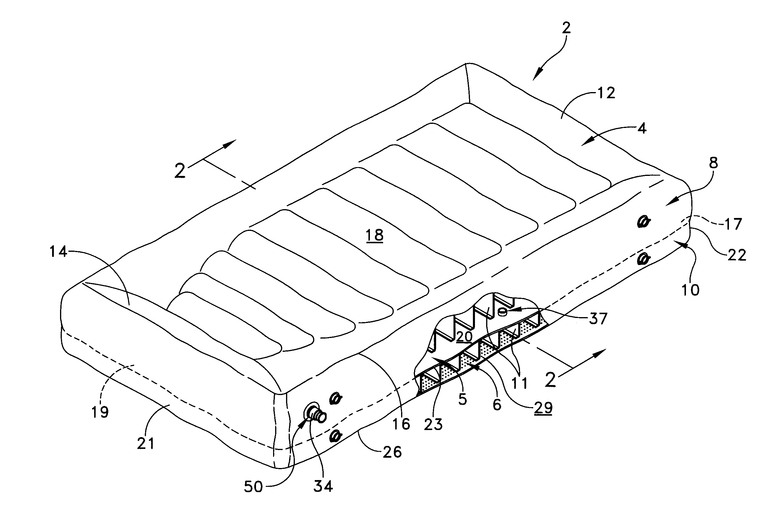
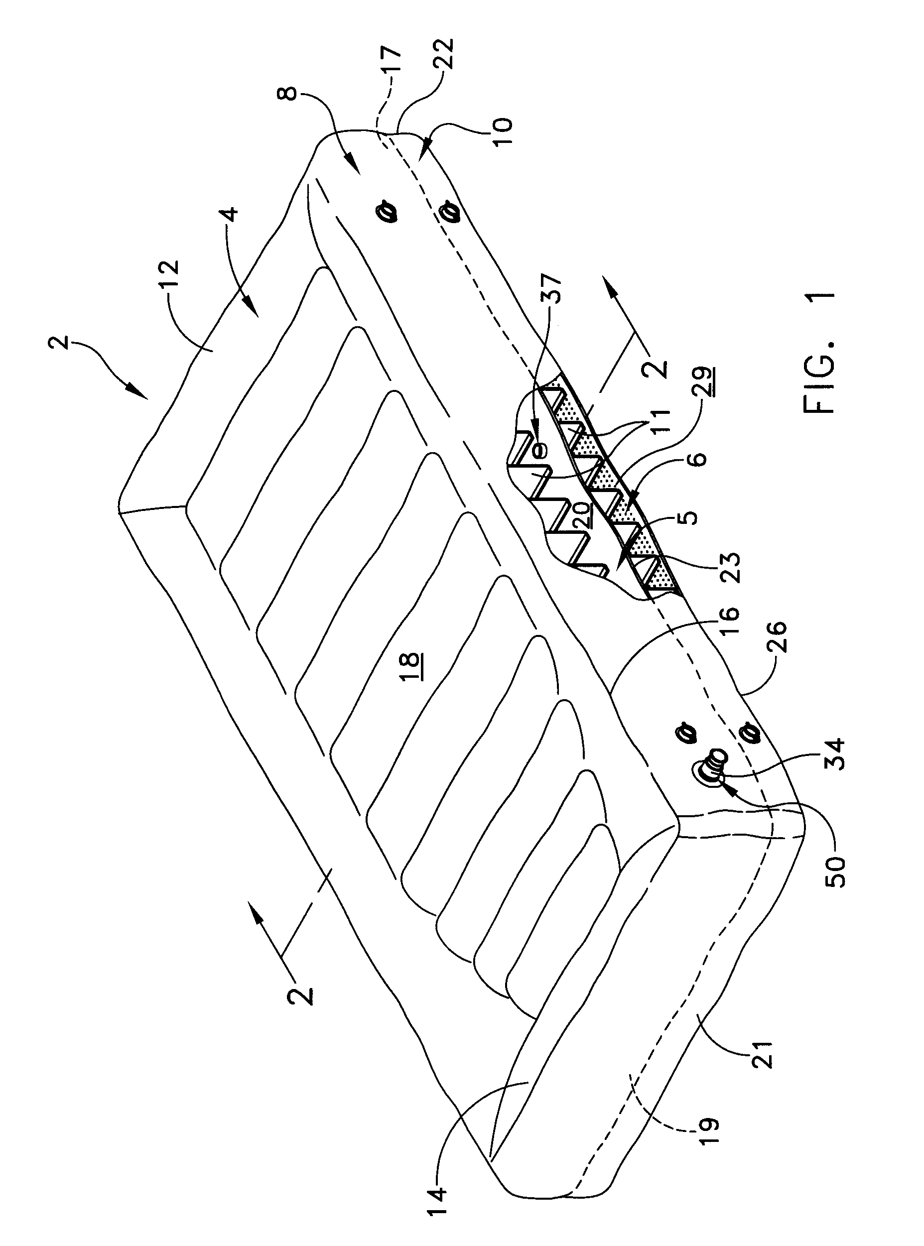
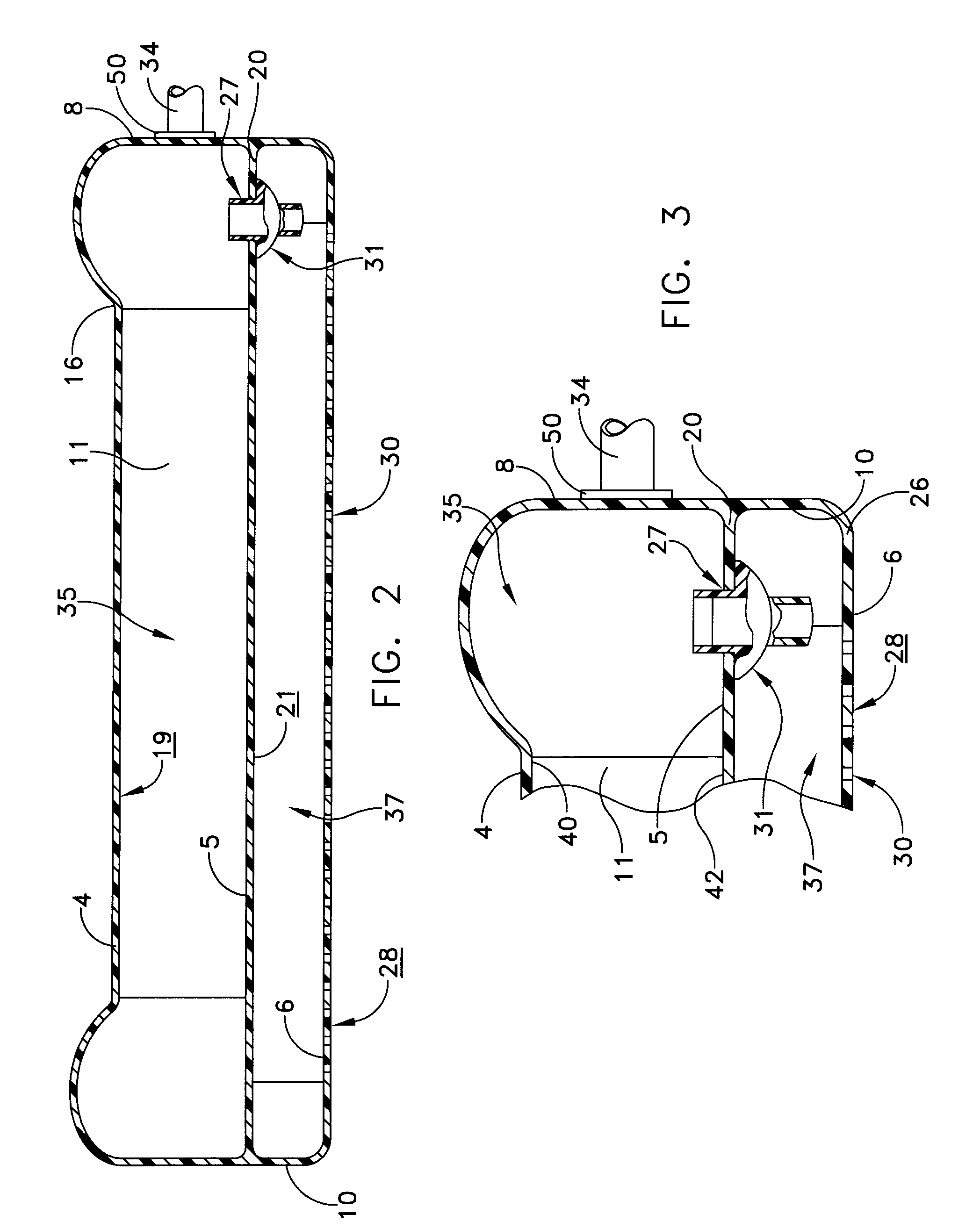
[0009] The present invention provides a double chambered transfer mattress that is capable of partial deflation. In one embodiment, a transfer mattress is provided that includes a top inflatable mattress and a bottom inflatable mattress that are separated by a common wall from one another. The bottom inflatable mattress includes a plurality of holes or perforations disposed in a bottom panel. A selectable inlet / outlet valve is arranged for airflow communication between an interior chamber of the top inflatable mattress and a source of pressurized air. A one-way valve is positioned through the common wall so as to provide selective air flow communication between the top inflatable mattress and the bottom inflatable mattress so that when said inlet / outlet valve is closed-off from the source of pressurized air, the bottom inflatable mattress deflates by air escaping through the plurality of holes or perforations whereby the one-way valve is actuated so as to prevent deflation of the top inflatable mattress.
[0010] In another embodiment a top sheet is provided having a width, a length, and peripheral edges, an intermediate, barrier sheet having the same width, the same length, and peripheral edges, and a bottom sheet having the same width, the same length, peripheral edges and a plurality of perforations. A first perimeter band is sealingly fastened between the peripheral edges of the top and barrier sheets and a second perimeter band is sealingly fastened between the peripheral edges of the barrier and bottom sheets. The peripheral edges of the top, barrier, and bottom sheets are sealingly fastened to the respective perimeter bands by heat sealing. A plurality of baffles, each having a width and a length, are attached to an inner surface of the top sheet and the barrier sheet so as to be oriented between the top sheet and the barrier sheet. A second plurality of baffles, each having a width and a length, are attached to an inner surface of the barrier sheet and an inner surface of the bottom sheet so as to be oriented between the barrier sheet and the bottom sheet. One or more inlet / outlet openings are located within the perimeter bands so that the double chambered transfer mattress may be inflated or deflated. Advantageously, one or more one-way valves are located through the barrier sheet so as to provide selective air flow communication between a first chamber formed between the top sheet, the barrier sheet, and the first perimeter band and a second chamber formed between the barrier sheet, the bottom sheet, and the second perimeter band. In this way, an inlet / outlet located in the first perimeter band may be closed-off from the source of pressurized air so that the second chamber deflates by air escaping through the plurlaity of holes or perforations. As the second chamber deflates, the one or more one-way valves are actuated so as to present deflation of the first chamber.

Problems solved by technology

All of the foregoing devices have suffered from an inability to be used during X-ray imaging of a patient lying upon the mattress.
Prior art transfer mattresses tend to drift or move, and are easily moved by even small perturbations.
Unfortunately, when deflated, the patient is forced to lie upon a very stiff table that can be quite uncomfortable for heavier patients.
Many of the foregoing devices also suffer from the fact that when uninflated they tend to bunch causing photo images to appear upon the x-ray exposures that mask underlying physiological features of the patient.

Method used


Image

  • Double chambered air mattress
  • Double chambered air mattress
  • Double chambered air mattress

Examples


Embodiment Construction

[0017] This description of preferred embodiments is intended to be read in connection with the accompanying drawings, which are to be considered part of the entire written description of this invention. The drawing figures are not necessarily to scale and certain features of the invention may be shown exaggerated in scale or in somewhat schematic form in the interest of clarity and conciseness. In the description, relative terms such as “horizontal,”“vertical,”“up,”“down,”“top” and “bottom” as well as derivatives thereof (e.g., “horizontally,”“downwardly,”“upwardly,” etc.) should be construed to refer to the orientation as then described or as shown in the drawing figure under discussion. These relative terms are for convenience of description and normally are not intended to require a particular orientation. Terms including “inwardly” versus “outwardly,”“longitudinal” versus “lateral” and the like are to be interpreted relative to one another or relative to an axis of elongation, o...


PUM


Abstract

A double chambered transfer mattress is provided capable of partial deflation that that includes a top inflatable mattress and a bottom inflatable mattress that are separated by a common wall from one another. A selectable inlet / outlet valve is arranged for airflow communication between an interior chamber of the bottom inflatable mattress and a source of pressurized air. A one-way valve is positioned through the common wall so as to provide selective air flow communication between the top inflatable mattress and the bottom inflatable mattress so that when the inlet / outlet valve is closed, so that air continues to escape from perforations in the bottom inflatable mattress, the one-way valve is actuated so as to prevent deflation of the top inflatable mattress.

Description

CROSS-REFERENCE TO RELATED APPLICATIONS [0001] This application is a continuation-in-part application of copending U.S. application Ser. No. 11 / 191,674, filed on Jul. 28, 2005, which itself claims priority from co-pending Provisional Patent Application Ser. No. 60 / 592,251, filed Jul. 28, 2004, and entitled DOUBLE CHAMBERED AIR MATTRESS.FIELD OF THE INVENTION [0002] The present invention generally relates to patient transfer devices and, more particularly to a patient transfer apparatus which employs an air bearing to facilitate the transfer. BACKGROUND OF THE INVENTION [0003] Patient handling mattresses are known in the art which include at least two flexible material sheets, that together define a plenum chamber, with at least one sheet being perforated with small pinholes over at least a central surface area, and which open up directly to the interior of the plenum chamber. Such prior art mattresses are used by arranging the perforated sheet so that it faces an underlying fixed, g...

Claims


Application Information

Patent Timeline
Patent Type & Authority Applications(United States)
IPC IPC(8): A47C27/10
CPCA61G7/1021A61G2200/32A61G7/1028A61G7/1026
Inventor DAVIS, DAVID
Owner D T DAVIS ENTERPRISES LTD D B A HOVERTECH INT
Learn More