
Desmodromic valve system and retrofit kit for conventional pushrod engines including replaceable cam lobes for adjusting lift and duration and hydraulic lifters for increased reliability

Inactive Publication Date: 2007-01-11
DECUIR JR JULIAN A
View PDF3 Cites 8 Cited by
  • Summary
  • Abstract
  • Description
  • Claims
  • Application Information

AI Technical Summary

Benefits of technology

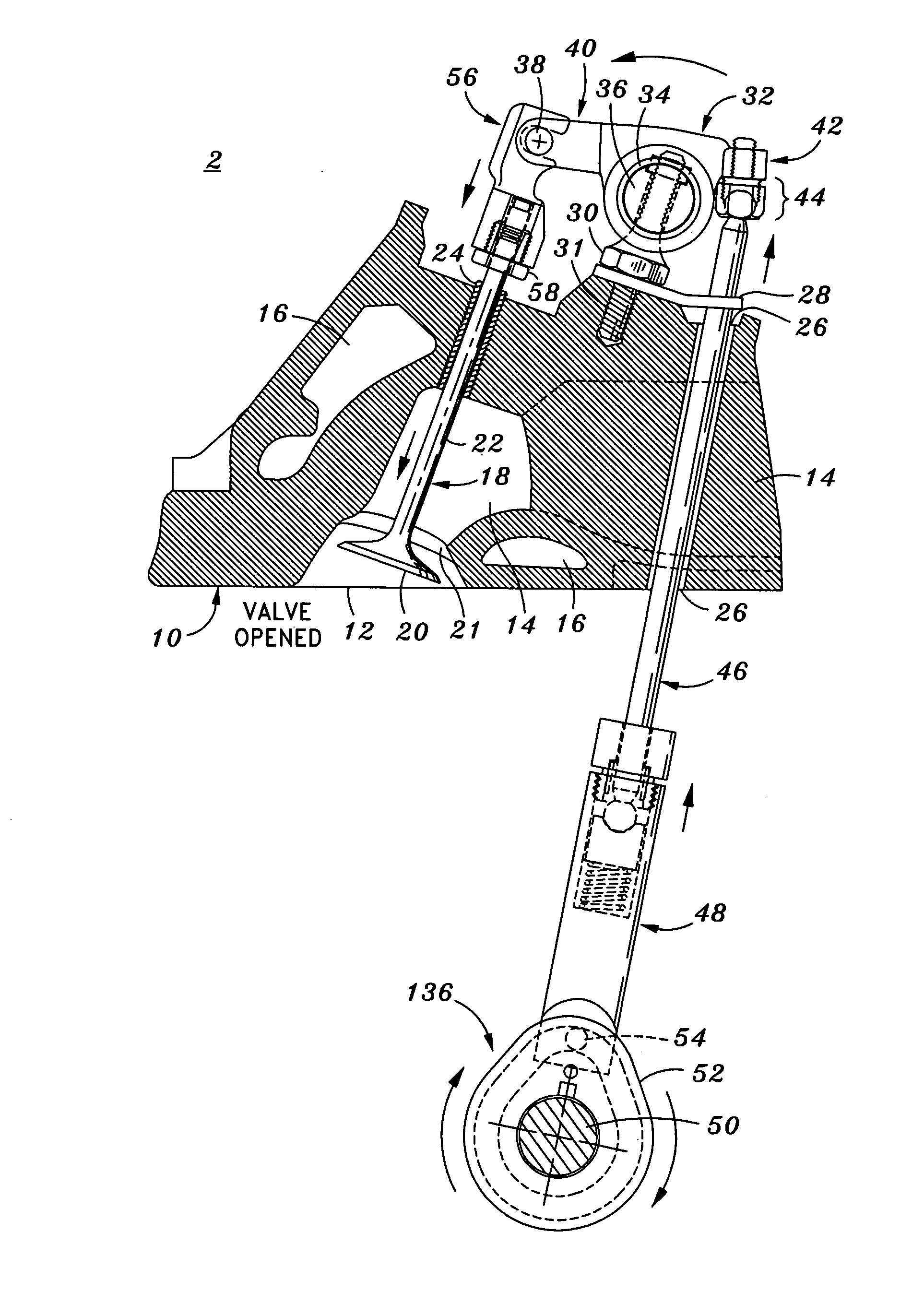
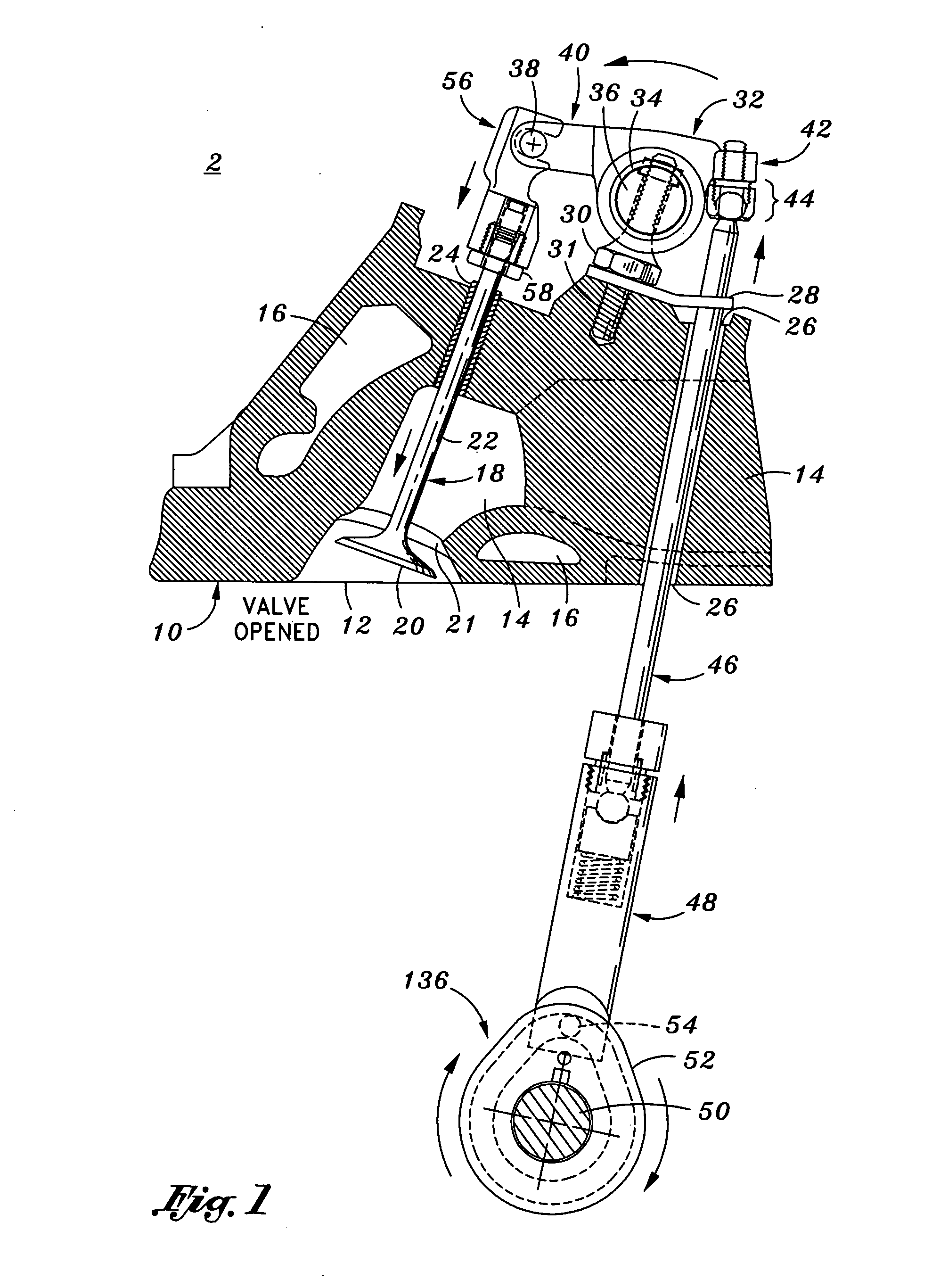
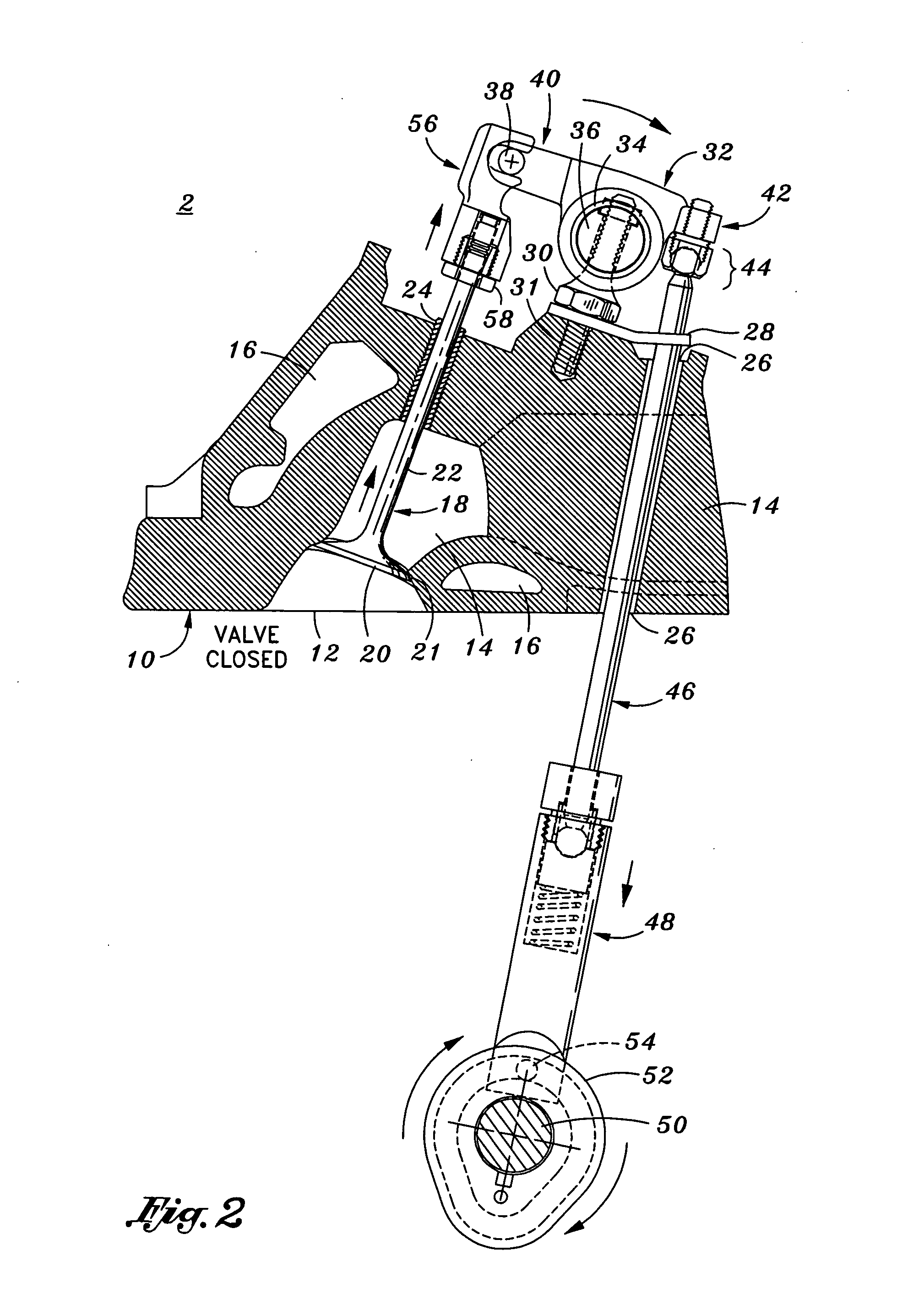
[0014] The present invention provides a desmodromic valve and cam system which utilizes hydraulic lifters and replaceable cam lobes that may be integrated into a new engine design or of which may be retrofit into an existing conventional pushrod engine without requiring the engine block, head or valves to be replaced or reworked. The present invention operates more efficiently than conventional valvetrains since binding tension is reduced from the valvetrain resulting in greater horsepower, better fuel economy and reduced emissions; while the incorporation of hydraulic lifters or the like makes the present invention desmodromic system more reliable. By providing a retrofit desmodromic system, the cost of installing the present invention into a vehicle is significantly reduced. Furthermore, the present invention is simple to manufacture and may be retrofit onto conventional pushrod type engines which are one of the most popular and successful automotive engines ever produced. Furthermore, the present invention's interchangeable cam lobe kits may be utilized on the same system, thereby, providing a wide array of adjustability in regards to being able to tune the engine's performance characteristics.
[0027] According to another embodiment of the present invention, a desmodromic valve and cam system retrofit kit for a pushrod engine is provided. The kit may include, but is not limited to, a main camshaft assembly having removable cam lobes, each cam lobe having mounting hole formed there through, and follower groove formed in at least one side of the cam lobe; a valve connector assembly adapted to be installed onto a distal tip of each valve of the engine; a rocker having a valve movement end and pushrod connecting end, the valve movement end being adapted to be mechanically linked to a respective valve connector assembly such that the rocker can either push down or pull up a respective valve and the pushrod connecting end being adapted to be mechanically linked to an upper distal end of a pushrod such that the rocker can either push down or pull up a respective pushrod; a hydraulic lifter follower assembly assigned to each valve which is adapted to be received within a lifter seat disposed within the engine block, each lifter assembly having a connecting means disposed on a distal end thereof which is adapted to engage and track a respective follower groove on a respective cam lobe; and a pushrod assigned to each valve, each pushrod having an upper and lower distal end, the upper distal end adapted to mechanically linked to the pushrod connecting end and the lower distal end adapted to be mechanically linked to a respective hydraulic follower lifter. As a result of the configuration of the aforementioned kit, the conventional valve springs may be moved from the engine's valvetrain, thereby increasing horsepower, fuel efficiency while reducing emissions.

Problems solved by technology

Most notably, pushing the valves open against the force of the springs consumes engine power.
Another disadvantage is that because the cam mechanism cannot afford to have any “bounce” from the springs, the cam profile has to be somewhat gentle, i.e., it must gently push the valve.
Another disadvantage is that when the motor is turned at high RPM's, the valves can “float” and hit the piston.
As a result, the valves will often stay open and / or “bounce” on their seats.
To overcome these disadvantages, innovative desmodromic valve trains have evolved over about the last century; however, in a very slow technological pace and in most applications with little or limited success.
Nevertheless, even though desmodromic valve trains have the aforementioned advantages, they have had limited success in large scale commercial applications due to reliability issues, complexity of design, and valve train binding to name a few reasons.
For instance, one of the major disadvantages of desmodromic valve trains is their sensitivity to change in size of the separate components of the system.
Also, the components of the valve train wear, thereby, decreasing the size of the components.
The end results are components such as valves which do not seat properly, or unwanted binding in the valve train.
Therefore, one of the major difficulties of prior art desmodromic valve train systems is the critical and accurate adjustment of various working components to ensure that the components operate together as intended without being subjected to binding, tension or excessive friction which results from the change of size in the individual components.
Another one of the problems with the aforementioned desmodromic valve train systems is that they have not been adapted to be installed or “retrofit” into existing modern conventional pushrod engines.
Unfortunately, however, most manufacturers are not willing to invest the sizeable amounts of capital to build such desmodromic engines, or much less, market vehicles with engine platforms which have not been proven or which have had a past history for reliability problems.

Method used


Image

  • Desmodromic valve system and retrofit kit for conventional pushrod engines including replaceable cam lobes for adjusting lift and duration and hydraulic lifters for increased reliability
  • Desmodromic valve system and retrofit kit for conventional pushrod engines including replaceable cam lobes for adjusting lift and duration and hydraulic lifters for increased reliability
  • Desmodromic valve system and retrofit kit for conventional pushrod engines including replaceable cam lobes for adjusting lift and duration and hydraulic lifters for increased reliability

Examples


Embodiment Construction

[0040] The particulars shown herein are by way of example and for purposes of illustrative discussion of the embodiments of the present invention only and are presented in the cause of providing what is believed to be the most useful and readily understood description of the principles and conceptual aspects of the present invention. In this regard, no attempt is made to show structural details of the present invention in more detail than is necessary for the fundamental understanding of the present invention, the description taken with the drawings making apparent to those skilled in the art how the several forms of the present invention may be embodied in practice.

[0041] The present invention provides a desmodromic valve and adjustable cam system for a conventional pushrod combustion engine which eliminates the use of valve springs normally used to close poppet valves. The system may be retrofit onto an existing engine design or which the features thereof may be integrally includ...


PUM


Abstract

A desmodromic valve and cam system is provided which is adapted to be installed into an internal combustion pushrod engine. The system includes a camshaft assembly having a plurality of removably attached cam lobes installed onto a main camshaft; a valve connector assembly installed onto a distal tip of each valve; a rocker having a valve movement end mechanically linked to a respective valve connector and a pushrod connecting end mechanically linked to an upper distal end of a pushrod; a hydraulic lifter follower assembly assigned to each valve which includes a pin disposed on a distal end thereof which is adapted to engage and track a follower groove formed on each respective cam lobe; and a pushrod assigned for each valve, each pushrod having lower distal end mechanically linked to a respective hydraulic follower lifter. The configuration of the aforementioned system eliminates the need to use valve springs to return the valves to a closed position, thereby, increasing horsepower and fuel efficiency, while simultaneously reducing emissions.

Description

CROSS-REFERENCE TO RELATED APPLICATIONS [0001] The present application is related to U.S. patent application Ser. No. 10 / 838,107, entitled “Desmodromic Valve and Adjustable Cam System,” filed on May 3, 2004 by inventor Julian A. Decuir, the content of which is expressly incorporated by reference herein in its entirety. [0002] The present application is also related to U.S. patent application Ser. No. 11 / 138,611, entitled “Desmodromic Valve Retrofit System with Replaceable Cam Lobes for Adjusting Duration & Hydraulic Lifters for Reliability,” filed on May 25, 2005 by inventor Julian A. Decuir, the content of which is expressly incorporated by reference herein in its entirety.STATEMENT RE: FEDERALLY SPONSORED RESEARCH / DEVELOPMENT [0003] Not Applicable BACKGROUND OF THE INVENTION [0004] 1. Field of the Invention [0005] The present invention relates to desmodromic valve and cam systems for traditionally configured internal combustion engines which utilize pushrods. In particular, the pr...

Claims


Application Information

Patent Timeline
IPC IPC(8): F01L1/30
CPCF01L1/042F01L1/047F01L1/146F01L1/181F01L2003/11F01L1/30F01L2001/0475F01L2001/0476F01L2001/2427F01L1/20F01L2001/054
Inventor DECUIR, JULIAN A. JR.
Owner DECUIR JR JULIAN A
Learn More