
Apparatus and method for acquiring and evaluating an image from a predetermined extract of a printed product

a technology of predetermined extract and image, which is applied in the field of apparatus and method for acquiring and evaluating an image from a predetermined extract of a printed product, can solve the problems of inability to ensure the accuracy of measured data during relatively long operation, inability to accurately reference the reference for zero light intensity, and inability to reduce measurement errors. the effect of reducing the cost of apparatus and high speed

Inactive Publication Date: 2007-01-11
GRAPHO METRONIC MESS UND REGELTECHN GMBH & CO
View PDF4 Cites 8 Cited by
  • Summary
  • Abstract
  • Description
  • Claims
  • Application Information

AI Technical Summary

Benefits of technology

[0012] In view of this prior art, the object of the invention is to provide an apparatus and a method for acquiring and evaluating an image from an extract of a printed product which makes it possible to determine characteristic variables of the printed product during its production in a press with the least possible expenditure on apparatus, both with high accuracy and at high speed.
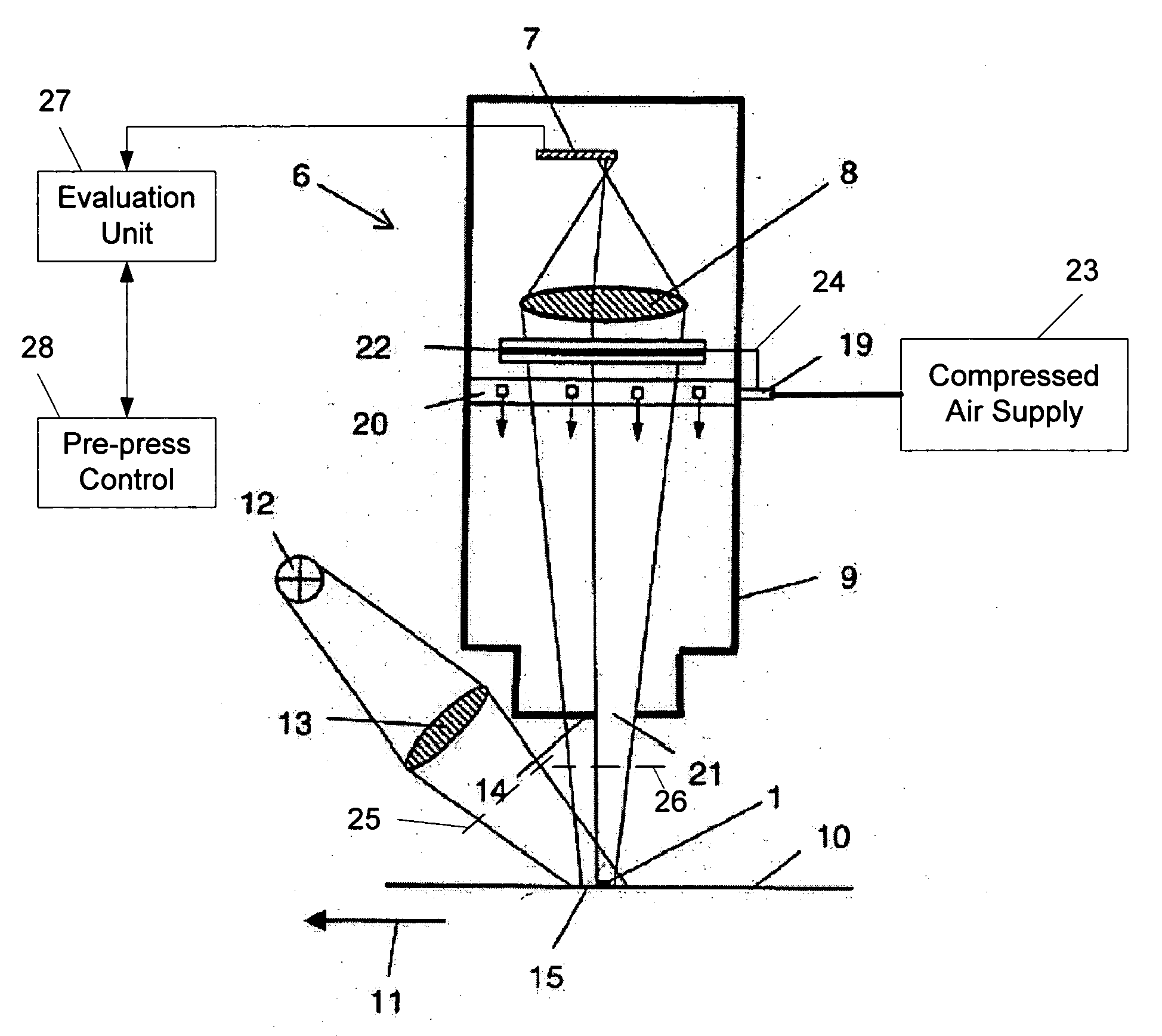
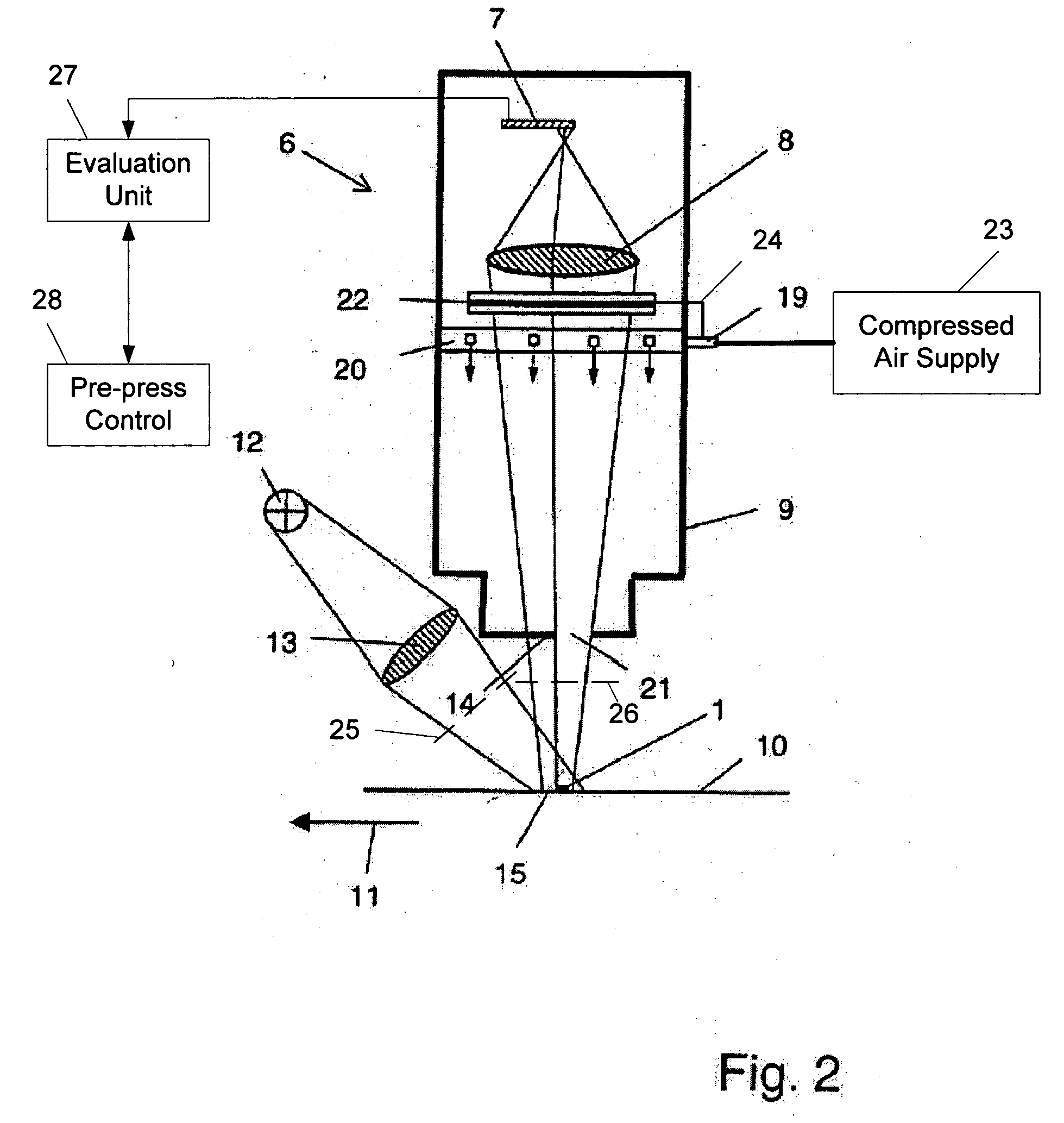
[0014] It is particularly advantageous if the aperture stop is shaped and arranged in such a way that the part of the image sensor shadowed by it extends next to an acquisition region of the image sensor that is used for the acquisition of the image of the extract of the printed product to be examined. The local proximity of the two parts of the image sensor in this case ensures particularly good agreement of the respective extent of incident scattered light. In this case, local proximity means that the distance of the shadowing region from the acquisition region is small as compared with the total dimensions of the image sensor. This distance is preferably also smaller than the extent of the acquisition region at a right angle to its edge lying closest to the shadowing region. Direct adjacency of the two regions is the closest possible form of proximity and, to this extent, is optimal but not absolutely necessary.
[0017] In order to keep the extent of the scattered light incident on the sensor as low as possible from the start, it is advantageous if the camera has a housing which is blackened, at least on the inside, which surrounds the objective and the image sensor and on or in which the aperture stop is also fitted.
[0026] The high measuring frequency that can be achieved with the invention permits the use of the characteristic variables determined for the regulation of processes in a press during continuous operation. For example, in particular ink density values can be used for regulating the ink supply in the inking unit of the machine.
[0027] Instead of a control strip specifically provided for the purpose, part of the subject being printed can also be projected onto the image sensor, registered by the latter and evaluated in order to determine characteristic variables. In this way, the area needed for a control strip is saved and the removal of the control strip from the printed product by cutting it off is no longer required. In this case, the measuring areas can be defined by information from processes upstream of the printing process, in particular from the pre-press stage.

Problems solved by technology

These error sources include in particular the stray light falling onto the image sensor during the measurement.
Other error sources include inaccuracy in the references for the zero light intensity and the intensity of the light shone onto the printed product by the light source.
An error source with a considerable influence on the measurement accuracy is the scattered light, i.e., the incidence of light on a sensor element of the image sensor which does not come from that section of the area of a measuring area on a printed product associated with the relevant sensor element.
The known concepts for reducing measurement errors during the characterisation of printed products appear overall to be complex and time-consuming.
On the other hand, given only one acquisition of reference data and setting of compensating and correction parameters before the start of printing operation, the accuracy of the measured data during relatively long operation is not ensured.

Method used


Image

  • Apparatus and method for acquiring and evaluating an image from a predetermined extract of a printed product
  • Apparatus and method for acquiring and evaluating an image from a predetermined extract of a printed product
  • Apparatus and method for acquiring and evaluating an image from a predetermined extract of a printed product

Examples


Embodiment Construction

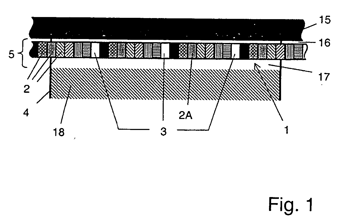
[0033] The application of the present invention in a preferred embodiment assumes that a control strip is provided on the printed product to be characterized. In the case of sheet printing, the control strip is printed on each sheet. In the case of an endless printing material web, the control strip is printed onto the web at regular intervals. Part of such a control strip 1 is illustrated schematically in FIG. 1. The strip 1 extends transversely with respect to the transport direction of the printed products in the press and, in its longitudinal direction, contains a periodic sequence of individual rectangular measuring areas 2.

[0034] The measuring areas are printed with different test patterns, each of which is designed for the determination of a specific characteristic variable by measurement. Typical examples of such test patterns are full-tone prints in the primary colors cyan, magenta, yellow and black for determining the respective ink densities. Furthermore, half-tone print...


PUM


Abstract

An apparatus for acquiring and evaluating an image of a predetermined extract of a printed product removes the effects of scattered light to improve the accuracy of image evaluation. The apparatus uses a camera that has an electronic image sensor with a two-dimensional arrangement of sensor elements. An aperture stop is arranged in the beam path of the camera for shadowing a predetermined part of the image sensor. When an acquired image is read from a part of the image sensor that is not shadowed, corresponding readings from the shadowed portion of the sensor are subtracted from the acquired image to obtain intensity signals corrected for scattered light.

Description

FIELD OF THE INVENTION [0001] The invention relates to an apparatus and method for acquiring and evaluating an image from a predetermined extract of a printed product, and more particularly to an arrangement for removing the effects of error sources such as scattered light to improve the accuracy of the image evaluation. BACKGROUND OF THE INVENTION [0002] During a printing operation, for the purpose of process monitoring, it is usual to provide printed control strips with colored test patterns outside the subject on sheets or webs to be printed. These control strips, whose longitudinal direction is transverse with respect to the transport direction of the printing material, contain a set of measurement areas which are repeated periodically in the longitudinal direction. A specific characteristic variable that characterizes the printing quality can be measured on each measurement area. [0003] For example, in the case of four-color printing, a typical configuration of a control strip ...

Claims


Application Information

Patent Timeline
IPC IPC(8): H01L27/00B41F33/00B41J29/46H04N1/00H04N1/028H04N1/04
CPCB41F33/0036H04N2201/02493H04N1/00002H04N1/00015H04N1/00023H04N1/00031H04N1/00045H04N1/0005H04N1/00055H04N1/00058H04N1/00087H04N1/0009H04N1/028H04N1/02805B41P2233/51
Inventor TATARCZYK, THEODORWEICHMANN, ARMIN
Owner GRAPHO METRONIC MESS UND REGELTECHN GMBH & CO
Learn More