Method for operating a primary beam stop

a beam stop and beam technology, applied in the direction of material analysis using wave/particle radiation, using wave/particle radiation means, instruments, etc., can solve the problem of inability to correct the varying properties of the beam optics, and achieve good radiation absorption and increase the measurement speed

Active Publication Date: 2007-01-11
BRUKER AXS
View PDF3 Cites 7 Cited by
  • Summary
  • Abstract
  • Description
  • Claims
  • Application Information

AI Technical Summary

Benefits of technology

[0012] In other words, in accordance with the invention, the diameter of the shielding projection of the beam stop in the detector plane (perpendicular to the beam axis, z-direction) can be set as desired. When the shadow cast by the beam stop exactly covers the beam spot of the primary beam and optionally parasitic radiation at the detector plane, the position of the beam stop is optimum. The diameter of the shielding projection can be adjusted to the experimental conditions, in particular to the exact dimensions of the components. Change of the shielding projection is easy to adjust in response to time-dependent changes of the properties of the beam optics.
[0022] In an alternative embodiment, the detector is a one-dimensional detector which can increase the measuring speed for measuring an angular or solid angular region.

Problems solved by technology

Secondly, there are temporally varying properties of the beam optics, such as e.g. temperature influences, aging effects, or varying experimental structures.
In this case, varying properties of the beam optics cannot be corrected.

Method used


Image

  • Method for operating a primary beam stop
  • Method for operating a primary beam stop
  • Method for operating a primary beam stop

Examples


Embodiment Construction

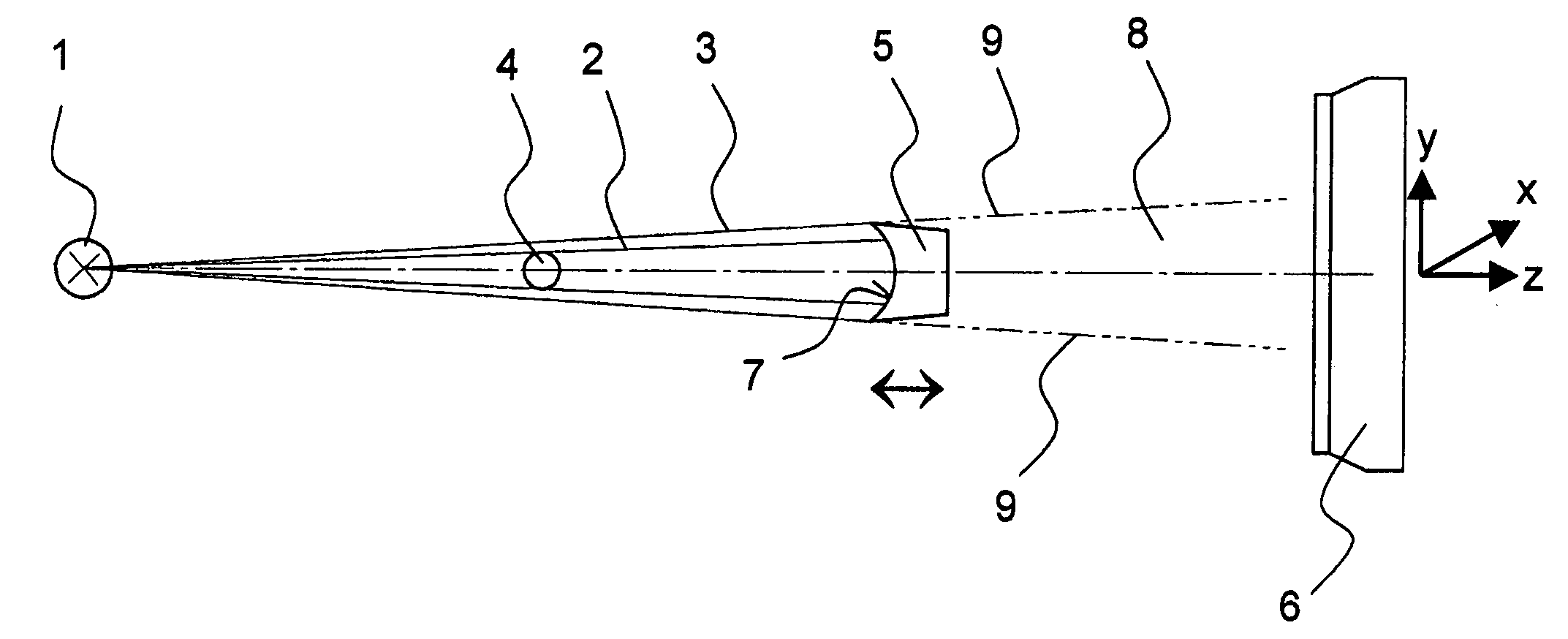
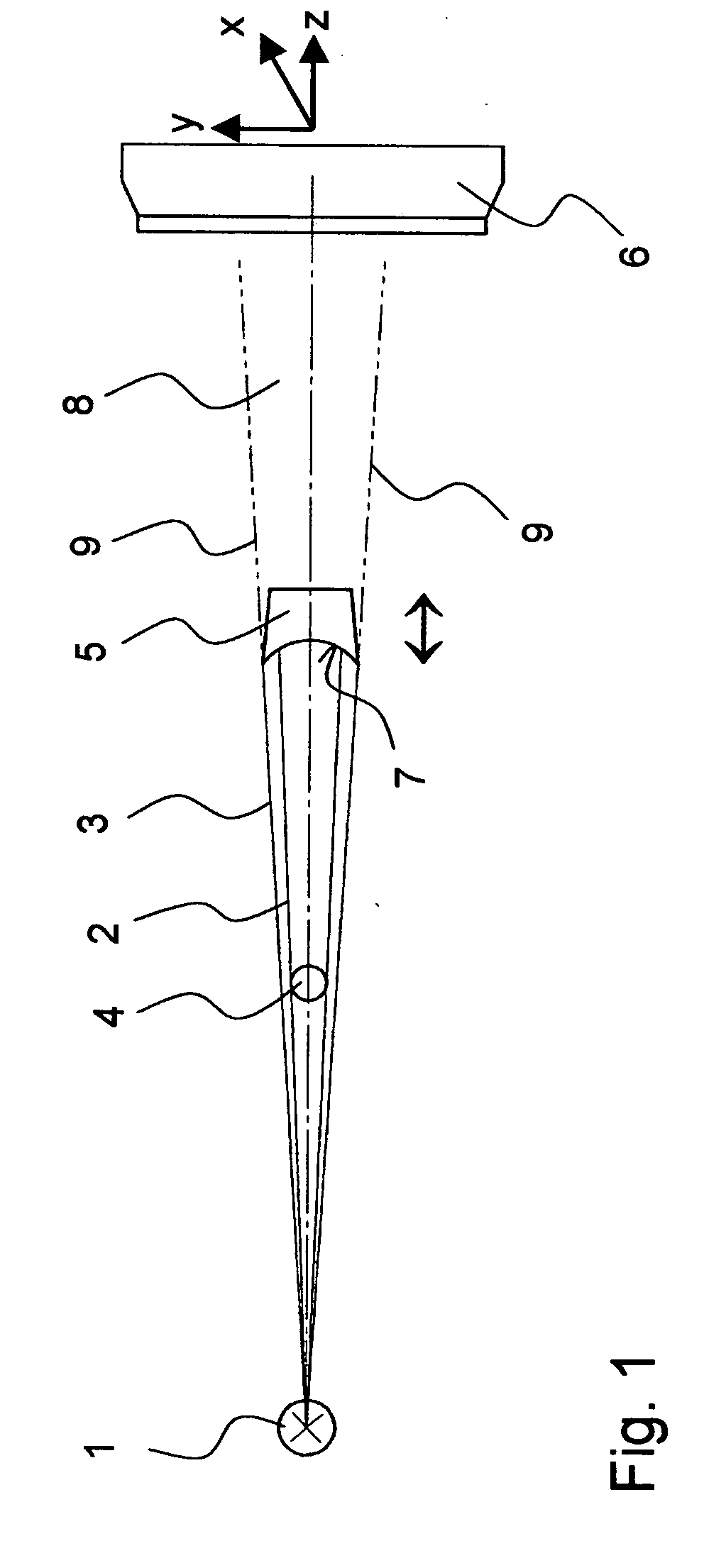
[0030]FIG. 1 shows the beam path of one embodiment of the inventive method for operating an X-ray or neutron-optical system. A source 1, which is shown highly schematically, emits radiation (X-ray or neutron radiation) along a z-axis. The emitted radiation is divergent (or convergent) i.e. its cross-section increases (or decreases) with increasing propagation in the positive z-direction. The radiation consists substantially of a conical primary beam 2 whose external edge region is surrounded by a conical surface of parasitic interfering radiation 3. The interfering radiation 3 can be produced e.g. through diffraction effects on collimators associated with the source 1. The source 1 denotes the device which generates the primary beam 2 impinging on the sample, i.e. a last mirror, a last diaphragm, or a last collimator behind an X-ray tube or a neutron emitter (which is often radioactive).

[0031] A sample 4 is disposed on the beam axis (z-axis) of the primary beam 2 and can be complet...


PUM

PropertyMeasurementUnit
angleaaaaaaaaaa
magnetic fieldaaaaaaaaaa
temperatureaaaaaaaaaa

Abstract

A method for operating an X-ray or neutron-optical system and beam stop comprising an X-ray or neutron source ( 1 ) from which corresponding radiation is guided as a primary beam ( 2 ) to a sample ( 4 ) under investigation, with an X-ray or neutron detector ( 6 ) for receiving radiation diffracted or scattered from the sample ( 4 ), wherein the source ( 1 ), the sample and the detector are disposed substantially on one line (=z-axis) and wherein a beam stop ( 5; 31; 41 ) is provided between the sample and the detector whose cross-sectional shape is adjusted to the cross-section of the primary beam is characterized in that the beam stop is disposed to be displaceable along the z-direction for optimum adjustment of the amounts of useful and interfering radiation impinging on the detector. This protects the detector from the influence of the primary beam while allowing a maximum amount of diffracted or scattered radiation to reach the detector, wherein the beam stop can be easily adjusted to temporally changing properties of the beam optics.

Description

[0001] This application is a divisional of Ser. No. 10 / 810,820 filed on Mar. 29, 2004 and also claims Paris Convention priority of DE 103 17 677.2 filed Apr. 17, 2003 the complete disclosure of which is hereby incorporated by reference.BACKGROUND OF THE INVENTION [0002] The invention concerns a method for operating an X-ray or neutron-optical system with an X-ray or neutron source from which associated radiation is guided as a primary beam to a sample under investigation, and with an X-ray or neutron detector for receiving radiation diffracted or scattered from the sample, wherein the source, the sample and the detector are substantially disposed on one line (=z-axis), and wherein a beam stop is provided between the sample and the detector, whose cross-sectional shape is adjusted, perpendicularly to the z-direction, to the cross-section of the primary beam. [0003] An X-ray optical system of this type is disclosed e.g. in the company document “HR-PHK for NanoSTAR” Instruction Handboo...

Claims


Application Information

Patent Timeline
Patent Type & Authority Applications(United States)
IPC IPC(8): G01T3/00G01N23/201
CPCG01N23/201
Inventor LANGE, JOACHIMSCHIPPER, ROLF-DIETER
Owner BRUKER AXS
Why Eureka
Try Eureka