Rotary actuator with non-contacting position sensor

a position sensor and rotary actuator technology, applied in the direction of resistor details, resistors with sliding contact, instruments, etc., can solve the problems of unknown position of the driven device, undesirable and dangerous, and achieve the effect of increasing reliability

Inactive Publication Date: 2007-01-11
CTS CORP ELKHART
View PDF90 Cites 16 Cited by
  • Summary
  • Abstract
  • Description
  • Claims
  • Application Information

AI Technical Summary

Benefits of technology

[0008] It is a feature of the present invention to provide an actuator with an int

Problems solved by technology

Unfortunately, in the case where there is a failure in the mechanical link between the actuator and the driven device, t

Method used


Image

  • Rotary actuator with non-contacting position sensor
  • Rotary actuator with non-contacting position sensor
  • Rotary actuator with non-contacting position sensor

Examples


Embodiment Construction

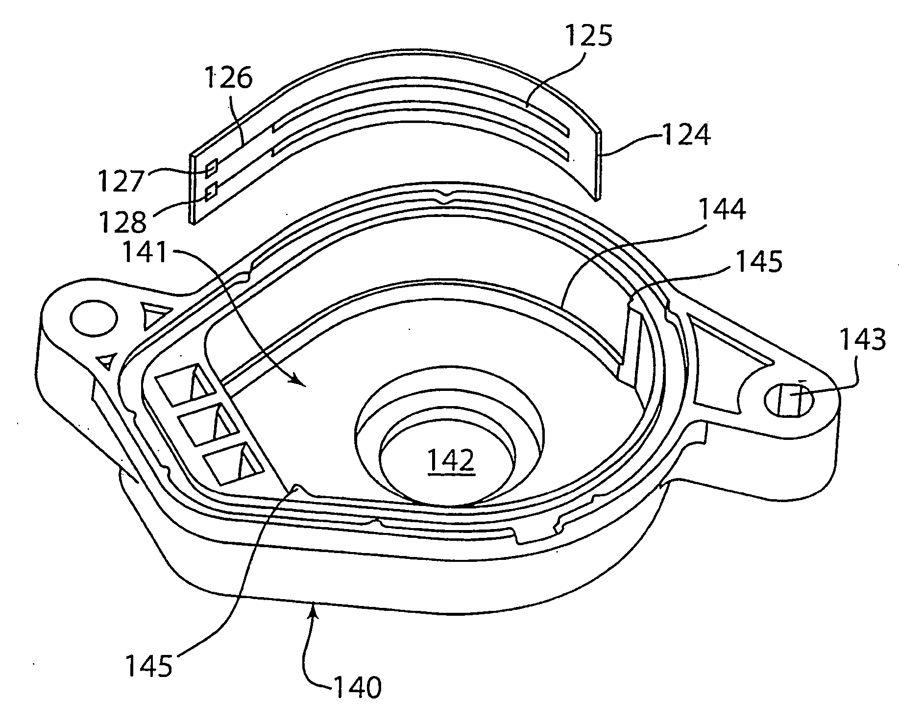
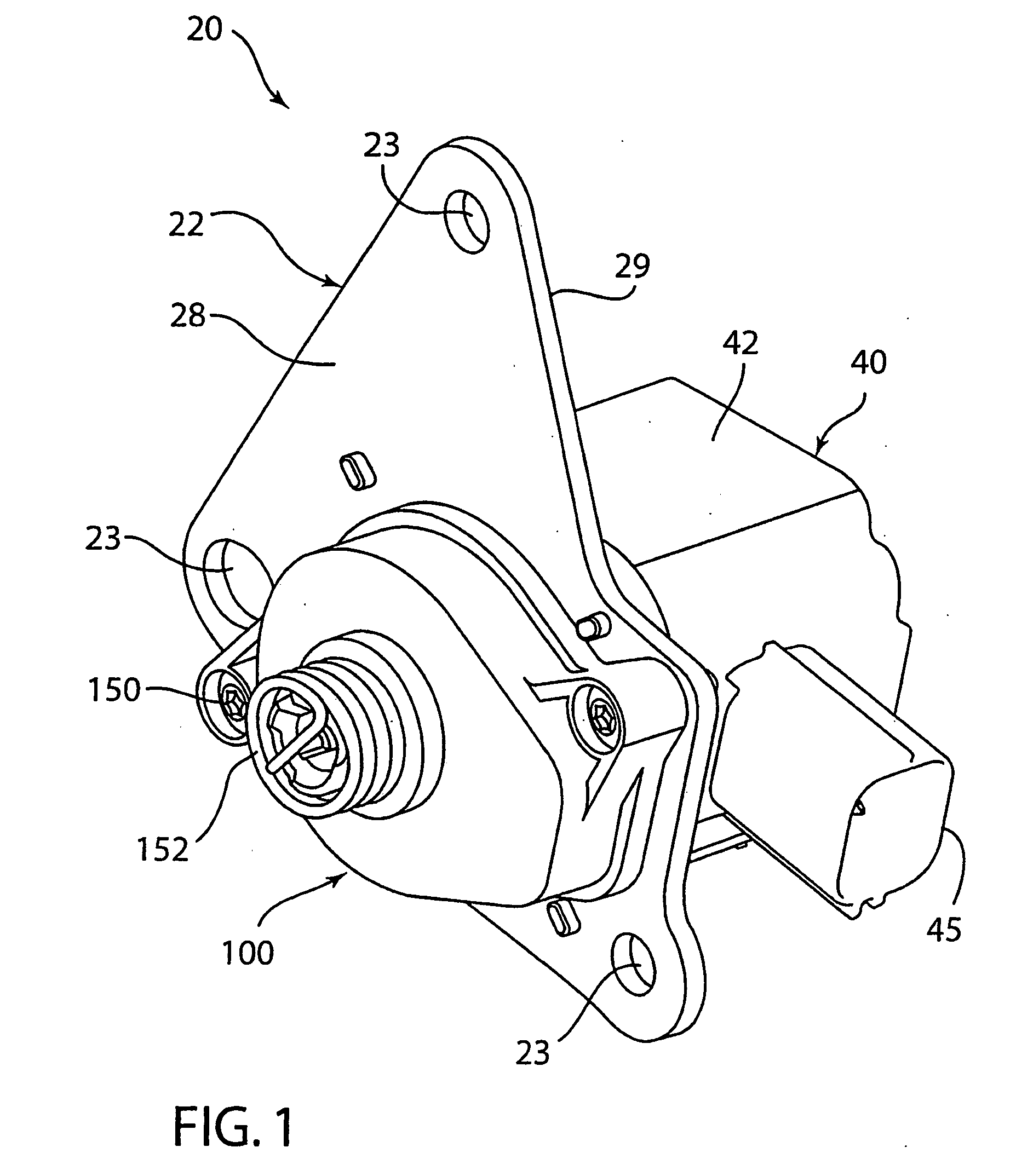
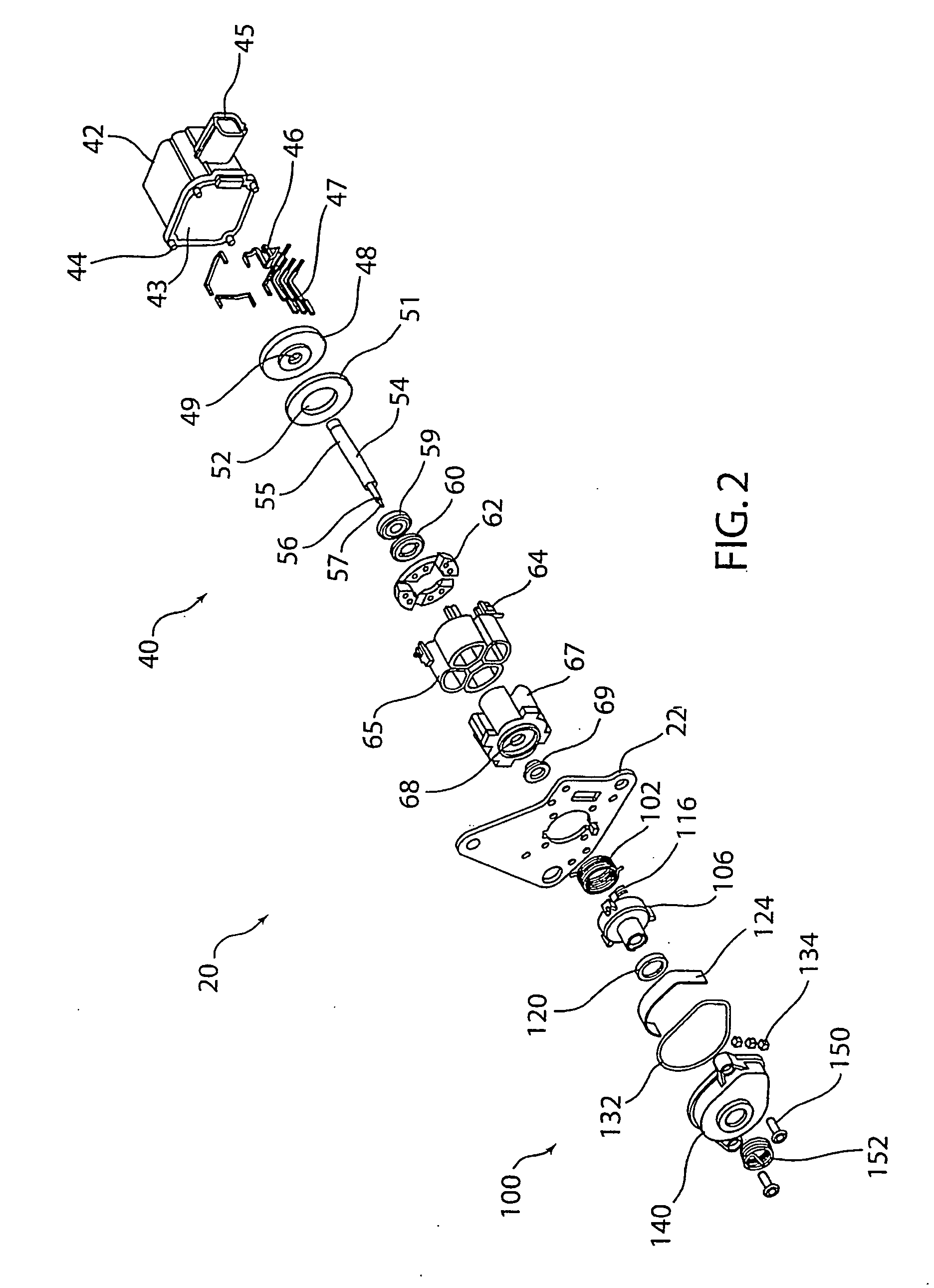
[0024] Referring to FIGS. 1-5, an embodiment of an actuator and sensor assembly 20 is shown. Actuator and sensor assembly 20 has an actuator 40 and a sensor 100. A bracket 22 is located between actuator 40 and sensor 100. Bracket 22 has a manifold mounting hole 23, a sensor mounting hole 24, a shaft hole 25, an actuator mounting hole 26, a slot 27, a side 28, a side 29, a notch 30 and a tab 31. Actuator 40 is mounted on side 29. Sensor 100 is mounted on side 28. Bracket 22 is mounted to an intake manifold 200 of an internal combustion engine. Screws 204 are fastened through manifold mounting holes 23 to hold assembly 200 to intake manifold 200.

Actuator

[0025] Actuator or electric motor 40 is a electro-mechanical stepper motor that has a high ratio of torque per mass and torque per power draw. Actuator 40 also has a magnetic circuit that allows a significant holding torque while using a limited amount of electric power.

[0026] Actuator 40 has a housing 42. Housing 42 has a cavity 4...


PUM


Abstract

An actuator and integral position sensor has increased reliability with a fail-safe mode. An electric motor has a shaft. A sensor is mounted to the electric motor. The sensor has a housing and a rotor. The rotor has a bore and first and second recesses. The recesses have different depths. The shaft is engaged with the bore. A first magnet is mounted in the first recess and a second magnet is mounted in the second recess. A magnetic field sensor is mounted adjacent the rotor.

Description

CROSS REFERENCE TO RELATED AND CO-PENDING APPLICATIONS [0001] The present patent application is a continuation-in-part of U.S. patent application Ser. No. 10 / 917,741, filed Aug. 13, 2004 and titled, “Actuator with Integral Position Sensor”. [0002] The present patent application claims priority to U.S. provisional patent application Ser. No. 60 / 749,531, filed Dec. 12, 2005 and titled, “Rotary Actuator with Non-Contacting Position Sensor”. [0003] The foregoing pending applications are herein incorporated by reference in their entirety.BACKGROUND [0004] The present invention relates to actuators in general and in particular to a rotary actuator with an integral position sensor. [0005] Prior actuators combined with position sensors have sensed the position of the actuator and not the device that is to be moved by the actuator. Unfortunately, in the case where there is a failure in the mechanical link between the actuator and the driven device, the position of the driven device is unknow...

Claims


Application Information

Patent Timeline
IPC IPC(8): H01C10/14
CPCG01D5/145H01C10/30H01C1/012G01D11/245
Inventor LAWRENCE, DONALD R.WANG, YULANDAPERIETEANU, FLORINMITCHELL, STEVEN R.
Owner CTS CORP ELKHART
Why Eureka
Try Eureka